Measurements and Assessments on Shielding Performance of FCTC10 60Co Transport Container
Article information
Abstract
Background
FCTC10 container is designed to transport 60Co radioactive sources used in irradiation industry. It belongs to Type B(U) Category III (yellow) package when being loaded with a 60Co source of 1.8×10⁵ Ci.
Materials and Methods
The container is constituted of shielding container, basket, protective cover and bracket. Shielding ability is provided mainly by stainless steel shells, tungsten alloy and lead among steel shells. Radiation level around the container has been calculated with both Monte Carlo simulations and measurements.
Results and Discussion
It is proven that the shielding performance of the container fulfills the requirements in GB11806-2004 (Regulations for the safe transport of radioactive material, China Standard Press). Exposure doses to workers and to critical groups of public were calculated based on hypothetical exposure scene according to transport practice experience.
Conclusion
The results show that doses to workers and public are less than the constraint dose considered in design, and the radiation level would be increased less than a factor of 2 under design basis accidents.
Introduction
With the rapid development of nuclear technology in industrial application, irradiation process is applied widely in various fields, such as medical disinfection and sterilization, food preservation, radiation chemical engineering, breeding, environment treatment, etc. Up to now, there are more than 200 large-scale γ irradiation facility with a total activity of more than 2.0×10⁸ Ci. In the US, irradiation sterilization facilities with an activity of about 1.0×10⁷ Ci were designed and constructed. In China, approximately 200 irradiation facilities were constructed, of which more than 100 facilities were designed to use sources of above 3.0×10⁵ Ci, while more than 40 facilities use sources of above 1.0×10⁶ Ci. Designed capacity of source loading is more than 1.0×10⁸ Ci, and the actual loading is about 3.6×10⁷ Ci [1].
60Co is a common used industrial irradiation source. At present, the activity of a 60Co source used in the large-scale irradiation facility is about 8,000 to 14,000 Ci, which is Category I source specified in GB11806-2004, and the transport contender loading such a source is Type B package, accordingly. FCTC10 container with a loading of 1.8×10⁵ Ci 60Co source is a Type B(U), Category III (yellow) package. Considering the high activity and potential hazards of 60Co source, the container should designed carefully, especially the shielding performance. According to the regulations of authority, tests including water spray, free drop, stacking and penetration for normal conditions of transport have been performed, while dropI, drop II, thermal test and water immersion have been carried out for accident conditions. In addition, simulations and measurements were conducted to verify design parameters [2, 3]. The design was approved by the Chinese authority in 2014.
Materials and Methods
1. Structure of FCTC10 container
As shown in Figure 1, the container consists of shielding container, hanging basket, protective cover and bracket. Shielding container comprises inner cask, lead plug, heat insulation, shock absorber. From inside out, the cask includes 10 mm inner stainless steel (0Cr18Ni9) shell, tungsten alloy bucket, protective cover, lead filling, and 16 mm outer stainless steel (0Cr18Ni9) shell. The tungsten alloy bucket has an outer diameter of 291 mm, a height of 614 mm, and a thickness of 42 mm on the upper side part, 62 mm on the side and 74 mm on the bottom. The protective cover is made of 5 mm stainless steel (0Cr18Ni9). The radial thickness of the lead filling is 147.5 mm. The lead plug consists a lead cylinder and a tungsten alloy cylinder stack. The lead cylinder has a radius of 154.5 mm and a height of 109 mm, while the tungsten alloy cylinder stack has an upper radius of 154.5 mm, upper height of 20 mm, lower radius of 86.5 mm, and lower height of 97 mm. The lead plug is covered with stainless steel (0Cr18Ni9), which is 2.2 mm thick on the side, 12 mm on the bottom, 3 mm in the middle and 25 mm on the top. The heat insulation comprises 6 mm stainless steel shells with 26 mm aluminum silicate fiber blanket in the middle.

Structure of FCTC10 transport container.
The hanging basket, which is 478 mm high and 140 mm in diameter, is placed in the middle of the container. The basket is a rod lattice structure and made of stainless steel (0Cr17Ni12Mo2). The protective cover of 1,264 mm×1,264 mm×1,414 mm consists of an angel steel frame, 4 lifting rugs, 4 side pull tab and a bottom steel net (0Cr18Ni9). The size of the steel frame is 1,250 mm×1,250 mm×230 mm, while the side of both top and bottom plates is 1,250 mm×1,250 mm×10 mm. The inner cask together with the tungsten alloy and lead fillings are mainly the components to provide shielding to the source.
2. Radiation level
1) Calculations
Monte Carlo codes have been used to calculate the radiation level outside the FCTC10 container with the maximum loading [4]. Only steel shells, tungsten alloy and lead fillings were considered in the calculation. The components of each material are listed in Table 1, and the simplified model used in the calculation can be found in Figure 2 Up to 19 60Co sources (total activity≤1.8×10⁵ Ci) can be loaded in the container. Calculated dose rates at different positions are shown in Table 2.

Composition of the Container Components
Shielding calculation model for FCTC10 container.
Calculated Dose Rates at Different Positions
2) Measurements
60Co sources of total 1.77×10⁵ Ci was used in the measurement. The activity of each source and the positions in the container can be found in Table 3 and Figure 3, respectively. The dose rates on the surface of the container, at the distance of 1 m and 2 m from the surface were measured with a FHZ612-10 (Thermo Fisher Scientific Inc., Waltham, MA) dose rate meter, which has a measuring range from 0.1 μSv·h−1 to 10 Sv·h−1, calibration factor of 0.98, and uncertainty of 5% (K=2). Measured results are list in Table 4.

Activity List of Radioactive Sources used in Test

Positions of radioactive sources in basket (top view).

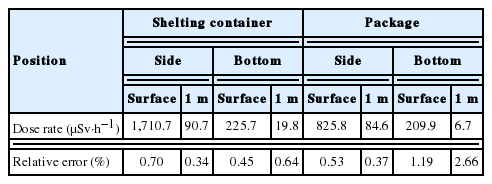
Maximum Dose Rates Measured Outside Package and Shielding Container (μSv·h−1)
3) Result
The maximum dose rates measured are on the side of the package and the shielding container, at the same height as the source. Calculated dose rates are listed in Table 5 together with measured results. Considering the size of the dose rate meter, the position used in calculations are not exactly the same as in measurements.

Comparison between MCNP Model Calculation Results and Measured Results (μSv·h−1)
FCTC10 container loaded with 60Co of 1.8×10⁵ Ci is Type B(U), Category III (Yellow) package. According to the regulations, the radiation level should not exceed 10 mSv·h−1 at any point on the external surface of the package, while it should be less than 0.1 mSv·h−1 at 1 m, if it’s not for exclusive use. Based on the design, radiation level should be less than 1.5 mSv·h−1 on the surface, and it should not exceed 0.098 mSv·h−1. The calculated and measured results show that the radiation level of the container with maximum activity of 60Co meets the design requirements.
Results and Discussion
1. Dose to the workers
During the transport of FCTC10 package, transport workers could be exposed to radiations in loading, transport and unloading. Based on experiences, exposure scenarios and dose to different kinds of workers, such as lifting workers, fastening workers and others. In the calculation, transport index of 9.8 was used. It can be found that, potential exposures to drivers and to escorts are higher than other workers. Based on Chinese national standards GB18871-2002 (Basic standards for protection against ionizing radiation and for the safety of radiation protection, China standard Press), the dose to radiation workers should be less than 20 mSv·a-1 (average of 5 years), but not to exceed 50 mSv in any year, while the dose constraint is 5 mSv·a-1 in GB11806-2004. To optimize protection and to keep the dose to works as low as reasonably achievable, the package should be as far as possible from the package, and shield should be used (see Table 6).

Exposure Parameters and Doses of Workers during Shipment
FCTC10 container passed tests required in GB11806-2004, with a minor reduction of shielding thickness (about 1 cm) [5]. Under design basis accidents, the radiation level outside the package would be increased less than a factor of 2.
2. Dose to the public
During road transport of TCTC10 package, residents, pedestrians, toll-gate workers, parking lot workers and so on could be exposed to radiations of the package. Transport by rail or by air would cause low exposure to the public. For transport by roads, dose to the public was calculated based on experiences. Based on GB18871-2002, the dose to the should be less than 1 mSv·a-1 (average of 5 years), but not to exceed 5 mSv in any year, while the dose constraint is 1 mSv·a-1 in GB11806-2004. The calculation results show that the transport of FCTC10 package would cause rather low dose to the public. To optimize protection to the public, the transport activities should be kept away from crowd.
Conclusion
According to the calculations and measurements, the position of maximum dose rate is on the side of the package. The maximum dose rate on the surface is 825.8 μSv·h−1, while it’s 84.6 μSv·h−1 at 1 m from the surface. The radiation level meet the regulations in GB11806-2004, and the design requirements for Type B(U), Category III (yellow) package.
Potential doses to transport workers and to the public have been calculated based on the experiments of transport activities, and transport index of 9.8 was used. The results show that potential dose to the driver is higher than to other workers, but it’s far less than the dose constraint of 5 mSv·a-1. For roadway transport, dose to the public is much lower than the limit required in national standards. Under design basis accidents, the radiation level outside the package would be increased less than a factor of 2.
Acknowledgements
The author would like to acknowledge Dr. Guoqing ZHANG, who is my schoolfellow and obtained a Ph.D. at Karlsruhe Institute of Technology in German, for his help to improve the English expression of the article.