

Introduction
In situ gamma-ray spectrometry is a useful method to directly identify radioactive deposits over a wide area of the ground resulting from a nuclear accident. The results from in situ gamma-ray spectrometry at 1 m above the ground can be particularly useful as reference values in mobile survey systems, such as backpack, carborne, and airborne surveys. Therefore, to make a good performance of the mobile survey system equipped with a gamma-ray spectrometer, it is advisable conduct the in situ measurement at 1 m above the ground using the same spectrometer before mounting in the mobile system. In general, a portable high purity Ge (HPGe) detector has been widely used for in situ gamma-ray spectrometry in the environment [1ŌĆō3]. This detector can produce reliable and stable results with the help of theoretical counting efficiency using in situ object counting system (ISOCS) software [2ŌĆō4]. However, there are drawbacks with respect to the expense of an HPGe detector, including the analysis software and its in situ operation, which affects detector cooling and portability. Therefore, diverse detector materials, especially scintillators with a high effective atomic number and good energy resolution, have been used in in situ measurement of gamma nuclides in radioactive material and in the environment as well for the calculation of dose rate and radioactivity [5ŌĆō8].
To evaluate radionuclides using in situ gamma-ray spectrometry, the counting efficiency and energy resolution are key points to be considered in the selection of a good detector. A scintillator, such as a large-volume plastic, CsI (Tl), and NaI (Tl), is generally used in radiation surveys of radioactive materials from a practical point of view, which means time and cost constraints. However, a scintillatorŌĆÖs poor energy resolution makes its application to the in situ gamma-ray spectrometry impractical; broad gamma-ray peaks are displayed due to interference with other gamma-rays emanating from different nuclides. Recently, cerium-doped lanthanum bromide LaBr3(Ce) scintillator, [9, 10], have proven highly attractive owing to having the highest energy resolution among commercial inorganic scintillators, although the intrinsic background in the material itself remains a problem to be overcome for detecting the environmental radiation with a relatively low count rate. In addition, this scintillator type shows good performance as a gamma-ray spectrometer, that is, it has high light output, high density, and fast decay time compared with other scintillators.
In this study, a 2ŌĆ│ŽĢ├Ś2.0ŌĆ│ LaBr3(Ce) scintillation detector (51S51_B380, Saint Gobain, Nemours Cedex, France) with an energy resolution of 2.6% at 662 keV was used to identify radionuclides distributed in the ground after subtraction of the intrinsic background of the detector. First, net count rates of gamma-rays emanating from radionuclides distributed in the ground were determined in the measured energy spectrum. By referring to International Commission on Radiation Units and Measurements (ICRU) Report 53 [11], the in situ calibration factor of the LaBr3(Ce) detector used, which means the counting efficiency at a given geometry to calculate the radioactivity concentration from a measured net count rate, was theoretically calculated using the Monte Carlo N-Particle (MCNP) code. The distribution of radionuclides in the ground was then assigned to be uniform in depth for natural radionuclides such as 214Pb, 214Bi, 228Ac, 212Pb, 208Tl, and 40K. In contrast, only surface distribution for 137Cs was assumed, which represents an early deposit in the ground. Finally, the results of the radioactivity concentration in the ground using the LaBr3(Ce) detector was compared with those of a portable HPGe detector at the same position.
1. Theory
According to the ICRU Report 53, the radioactivity distribution with the depth in the ground can be expressed in terms of Equation 1, as assuming the density of soil is constant in the ground.
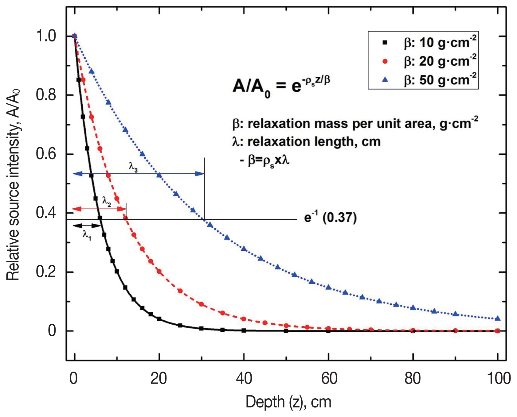
where, A0 is the radioactivity concentration at the surface (Bq┬ĘkgŌłÆ1), Žüs is the soil density (g┬ĘcmŌłÆ3), z is the depth in the ground (cm), ╬╗ is the relaxation length (cm), which means the depth in the ground that reduce the source intensity to eŌłÆ1 (37%) of its maximum intensity, as shown in Figure 1, ╬▓ is the relaxation mass per unit area (g┬ĘcmŌłÆ2) with a form of the multiplication of the relaxation length and soil density, which means the depth profile of deposited radionuclides in the ground, and A means the radioactivity concentration at a certain depth (Bq┬ĘkgŌłÆ1 or Bq┬ĘmŌłÆ2).
Because the recent fallout due to the release from nuclear facilities is distributed only in the surface of the ground, the relaxation length (╬╗) approaches to a zero value in Equation 1. Therefore, the radioactivity concentration is not existed in a certain depth of the ground. As time passes, the radionuclides in the surface are diffused into the depth of the ground and the relaxation length and mass per unit area have a certain integer to reflect the exponential depth profile of deposited radionuclides, as shown in Figure 1. To calculate the radioactivity concentration of deposited radionuclides with the depth, Equation 1 should be integrated according to Žüsz. The result is shown in Equation 2. Therefore, the radioactivity concentration of deposited radionuclides in the ground due to the radioactive fallout is generally expressed in the unit of Bq┬ĘmŌłÆ2.
On the other hand, because the natural radionuclides have a uniform intensity of radioactivity with the depth of the ground, the relaxation length (╬╗) approaches to an infinite value in Equation 1. This means the radioactivity concentration at a certain depth (A) should be the same with one at the surface (A0) in Equation 1. Therefore, the radioactivity concentration of natural radionuclides in the ground is expressed in the unit of Bq┬ĘkgŌłÆ1.
Materials and Methods
1. The LaBr3(Ce) detector
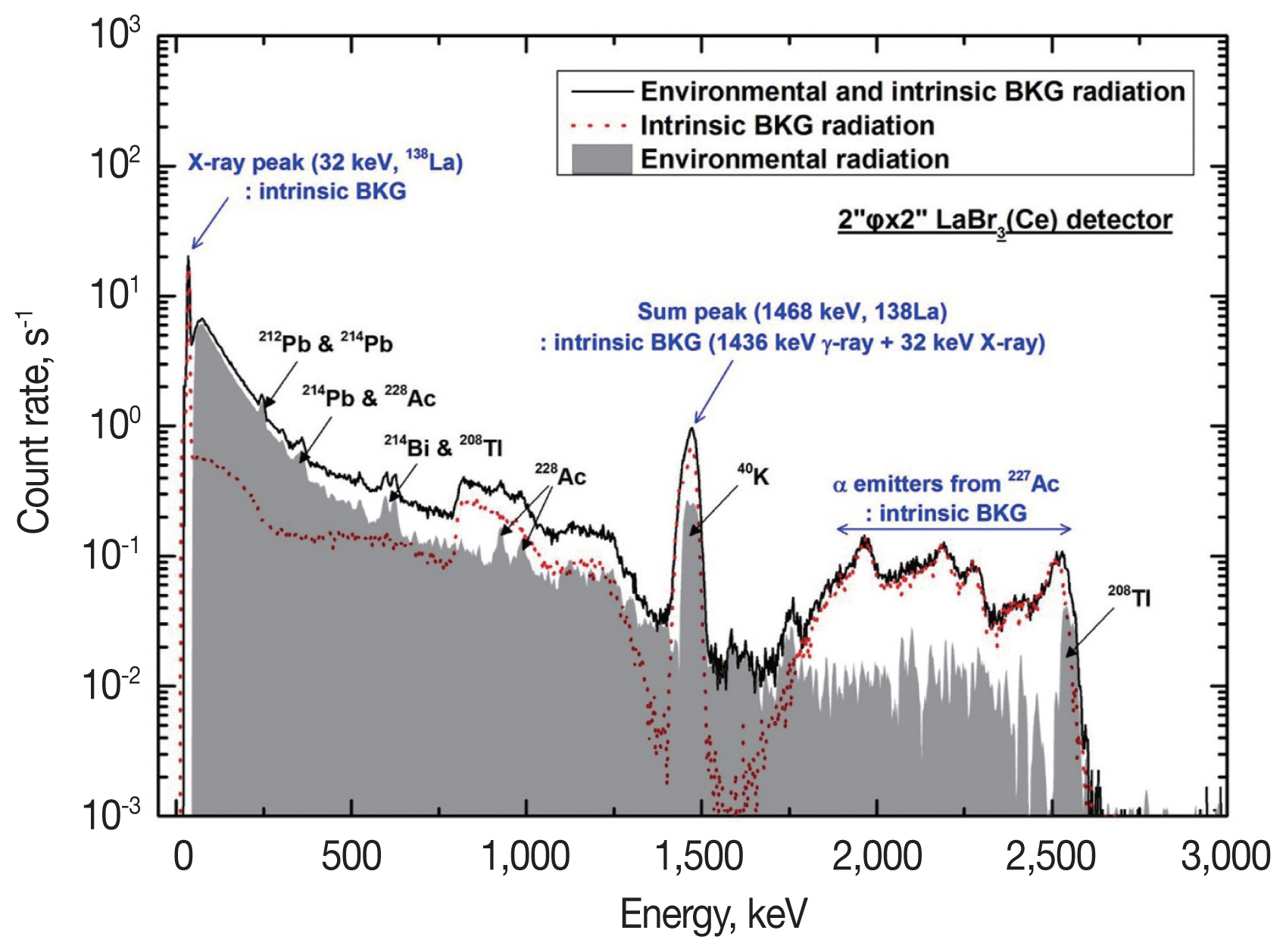
An LaBr3(Ce) scintillation detector demonstrates high performance in identifying gamma-rays with good energy resolution compared with other scintillators. However, this type of detector has intrinsic background radiations induced from 138La and 227Ac, which are radioisotopes existing in the natural lanthanum element with about 0.09% abundance, and with a chemically homologous property. Because they are in the scintillator material itself, the complicated intrinsic background energy spectrum is comprised of X- and gamma-rays emitted from 138La and their summing effect and alpha emitters in the progenies of 227Ac. Figure 2 shows an example of measured energy spectra using a 2ŌĆ│ŽĢ├Ś2.0ŌĆ│ LaBr3(Ce) detector. The solid line reflects measurement at 1 m above the ground with environmental and intrinsic background radiation, and the dotted line represents the intrinsic background energy spectrum of the LaBr3(Ce) detector, which was measured in a lead shield with a thickness of about 10 cm. The gray area is the energy spectrum of only environmental radiations after intrinsic background subtraction with a cut-off count rate below 50 keV.
An appropriate method should be prepared to subtract the contribution of intrinsic background radiations from the measured energy spectrum using an LaBr3(Ce) detector. In this study, a simple algorithm was developed by subtracting the count rate by the energy bin, from 1 to 1,024 bins, between two energy spectra in the environment and lead shield, after their energy calibrations. Two dominant peaks induced from the intrinsic background radiation, that is, an X-ray peak with an energy of 32 keV and its sum peak with a gamma-ray of 1,436 keV from 138La, are always detected in the measured energy spectrum in the environment as well as the lead shield. The energy calibration with a form of the linear regression can then be easily made by using two dominant peaks, because of its sufficient energy distance over the whole energy range. The re-arrangement of count rates by the energy bin was then conducted such that the energy difference in the same bin number between two spectra would be below 2 keV. Finally, the energy spectrum due to only environmental radiations without intrinsic background radiations was obtained by subtracting count rates, bin-by-bin, in the two energy spectra.
2. In situ calibration factor
From the measured net count rate, the radioactivity in the ground can be calculated by using the in situ calibration factor, as shown in Equation 3.
where, Ai is the radioactivity concentration in the ground by the nuclide, which is expressed in the unit of Bq┬ĘkgŌłÆ1 or Bq┬Ęm2 for natural and artificial radionuclides, respectively, (nŌĆ▓)E is the measured net count rate of gamma-rays with an energy E, ╬│E is the emission probability of a gamma-ray, and ╔øE and (nŌĆ▓/A╬│)E are the in situ calibration factor at a given geometry.
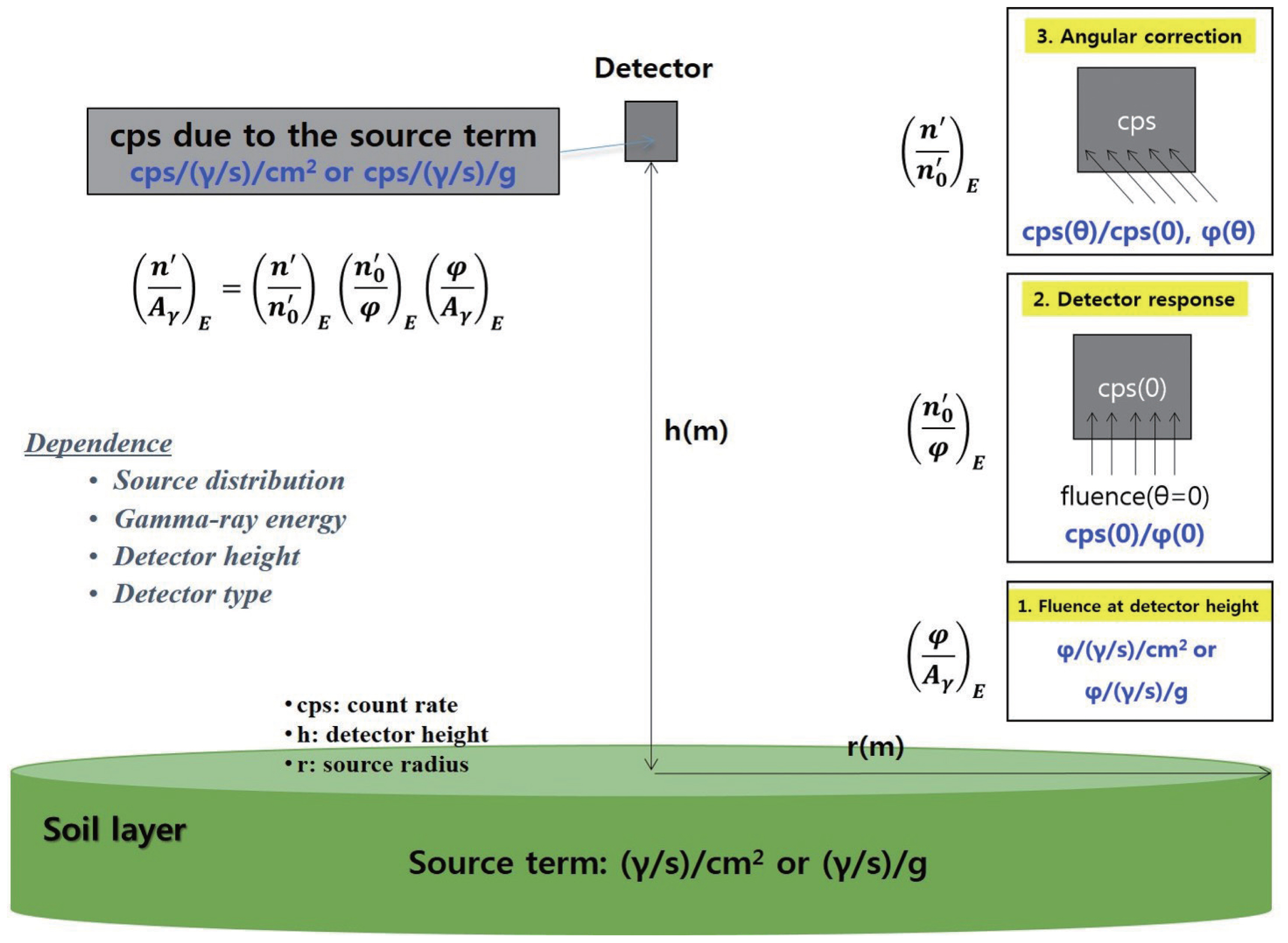
According to ICRU Report 53, the in situ calibration factor can be expressed as three variables, as shown in Equation 4. Its physical meaning is the theoretical count rate in a detector due to the source term in the ground, and it depends on the source distribution, gamma-ray energy, detector height, and detector type, as shown in Figure 3. In this study, the 2ŌĆ│ŽĢ├Ś2.0ŌĆ│ LaBr3(Ce) detector was already assigned to be located at 1 m above the ground, and the source term was assumed to be uniform and superficial distribution for natural and artificial nuclides, respectively.
where, (ŽĢ/A╬│)E is the unscattered gamma-ray fluence with energy E at the detector height due to the unit source term in the ground,
( n 0 ŌĆ▓ / ŽĢ ) E ( n ŌĆ▓ / n 0 ŌĆ▓ ) E
1) Unscattered gamma-ray fluence
In general, the angular distribution of unscattered gamma-ray fluence at the detector height, owing to the deposits in the ground, can be mathematically expressed as Equations 5 and 6 for the uniform distribution of natural radionuclides in the ground and superficial distribution representing the early deposit of artificial radionuclides, respectively [7, 8].
where, Žē is the cosine angle, A0 and Aa are the radioactivity per unit mass and one per unit area at the surface of the ground, Žüa is the density of air, ╬╝s and ╬╝a are the linear attenuation coefficient in soil and air, and h is the height from the ground to the detector.
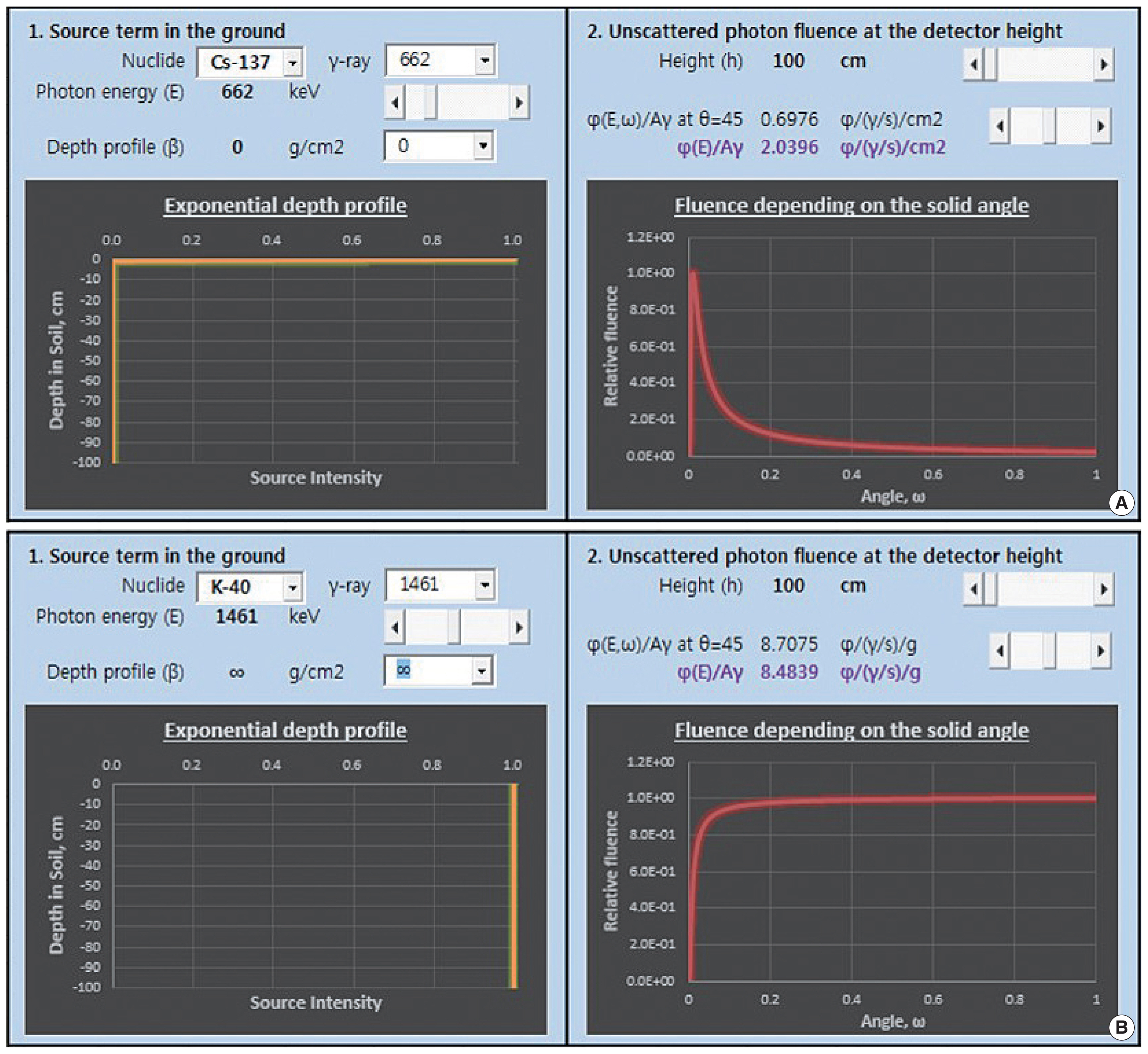
Finally, the unscattered gamma-ray fluence at the detector height, ŽĢ (E), can be calculated by integrating its angular distributions, ŽĢ (E, Žē), for whole cosine angles. MCNP simulation using a fluence tally can be directly applied to the calculation of the unscattered gamma-ray fluence. However, to meet the condition of the infinite half-space of the ground, there are some drawbacks that the source distribution should be sufficiently wide in the ground, above a 100 m radius [12, 13]. In this study, a simple program coded in Excel Visual Basic for Applications (VBA), as shown in Figure 4, was developed to directly calculate the unscattered gamma-ray fluence depending on the gamma-ray energy, depth profile (╬▓) in the ground, and detector height. Table 1 shows the calculated unscattered gamma-ray fluences at 1 m above the ground due to the uniform and superficial source distribution, respectively, and their comparisons with Health and Safety Laboratory (HASL) [14] and ICRU data [11]. A below 10% difference was generally maintained among them, and it is expected that their differences, especially in the HASL data, were induced from the data of attenuation coefficients used.
2) Detector response and its angular correction
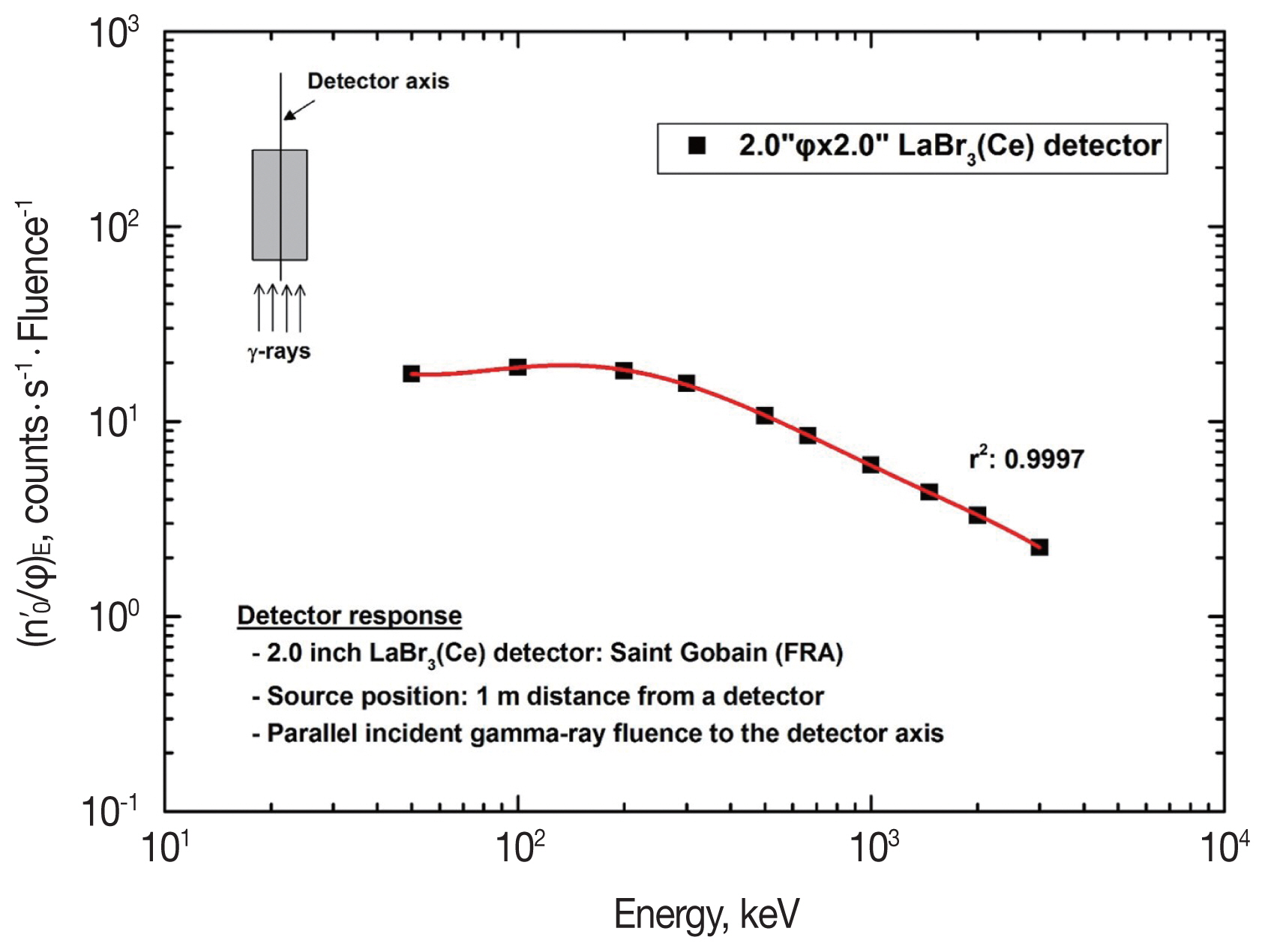
When the unscattered gamma-ray fluence previously calculated is incident to the detector, its response should be theoretically calculated to produce the in situ calibration factor. However, since their incident angles to the detector are different from each other, they have different responses in a detector. This makes the detector response angularly corrected. First, the detector response of the 2ŌĆ│ŽĢ├Ś2.0ŌĆ│ LaBr3(Ce) detector was calculated using the F8 tally (pulse height tally) of the MCNP code under the condition of parallel incidence of gamma-ray fluence to the detector axis after distributing unit gamma-ray fluence at a 1 m distance from the detector in the air. The net count rate by the energy of simulated gamma-rays was then determined in the theoretical energy spectrum from the MCNP simulation. Figure 5 shows the calculated detector response of the LaBr3(Ce) detector used for parallel incident gamma-rays. The six-order polynomial regression was successfully conducted in the log-log scale, and the polynomial coefficients were used to output the results according to the gamma-ray energy.
The angular correction factor is a function of the unscattered gamma-ray fluence at the detector position and angular dependence for the detector response [15], and its mathematical expression can be shown in Equations 7 and 8.
where, R (E, Žē) is the angular dependence of the detector response, and nŌĆ▓ (E, Žē) and
n 0 ŌĆ▓ ( E , Žē ) n 0 ŌĆ▓ ( E , Žē )
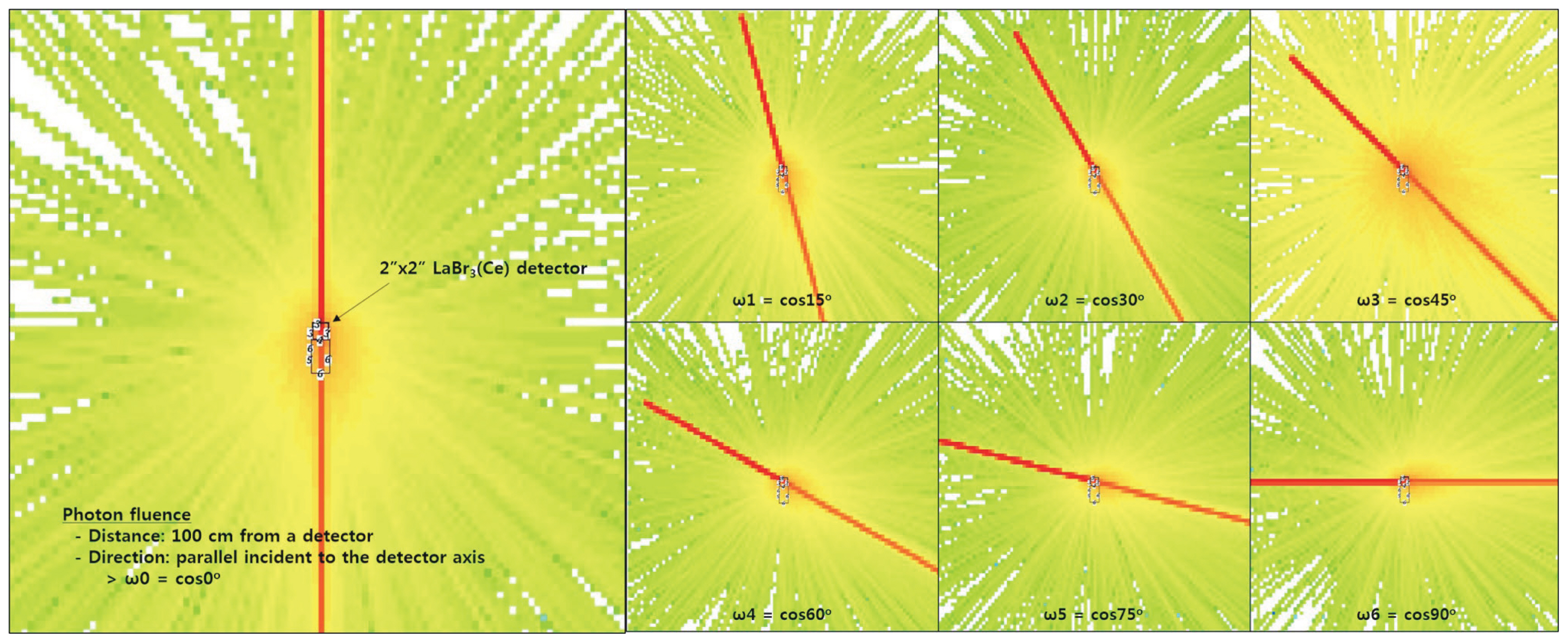
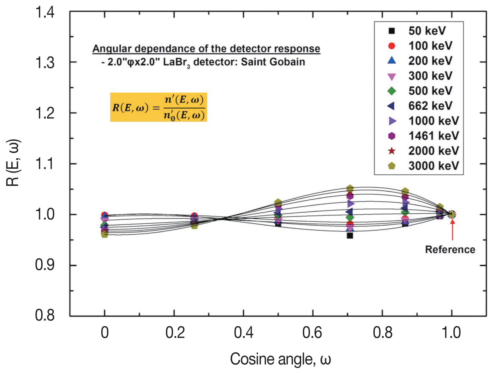
The gamma-ray fluence with a 1 cm radius was simulated in the air several cosine angles of 0┬░, 15┬░, 30┬░, 45┬░, 60┬░, 75┬░, and 90┬░ in a 1 m distance from the detector. The rotation angle was fixed to the center of a LaBr3(Ce) material. Through the calculation of theoretical net count rates according to the cosine angle using the MCNP code, the angular dependence of the detector response was obtained, as shown in Figure 7. Fourth-order polynomial regression was successfully conducted at linear scale, and the regression coefficients were coded to produce the results at arbitrary energies and solid angles. Finally, inserting them into Equation 7, the angular correction factor of the 2ŌĆ│ŽĢ├Ś2.0ŌĆ│ LaBr3(Ce) detector at 1 m height above the ground could be calculated by using the calculated unscattered gamma-ray fluence.
3. Method of the experimental verification
For the feasibility of the calculated in-situ calibration factor of the 2ŌĆ│ŽĢ├Ś2.0ŌĆ│ LaBr3(Ce) detector, in situ gamma-ray spectrometry was conducted at 1 m height above the ground. The results were then compared with those of a portable HPGe detector with a 40% relative efficiency (Length/Diameter of a crystal: 0.9342, GC4018, Canberra Inc., Meriden, CT) and ISOCS software to calculate the theoretical counting efficiency at the same position. First, natural radionuclides in the ground, including 214Pb, 214Bi, 228Ac, 212Pb, 208Tl, and 40K, were analyzed at the Korea Atomic Energy Research Institute (KAERI) site, on the assumption of their uniform distributions in the ground. Second, for the application to radioactive deposits, in situ gamma-ray spectrometry using the 2ŌĆ│ŽĢ├Ś2.0ŌĆ│ LaBr3(Ce) and portable HPGe detector was conducted to determine the radioactivity of 137Cs in the ground on Jeju Island.
Results and Discussion
1. The determination of in situ calibration factors
To calculate the radioactivity concentration of natural and artificial radionuclides in the ground from the measured net count rate of major gamma-rays emanating from them, the in situ calibration factor of the 2ŌĆ│ŽĢ├Ś2.0ŌĆ│ LaBr3(Ce) detector was calculated using the aforementioned methods. Table 2 shows the results of 137Cs and six natural radionuclides with superficial and uniform distribution in the ground, respectively, at 1 m above the ground. Three variables in the in situ calibration factor are shown from the fourth to fifth columns, and their multiplication is shown in the last column. In general, because the source term is expressed in the unit of the intensity per unit area or mass for the superficial or uniform distribution, the different units between them are shown in the unscattered gamma-ray fluence at detector height due to the source term in the ground. Therefore, the in situ calibration factor of the LaBr3(Ce) detector used at a given geometry, which means the height of 1 m from the infinite half-space of the ground, is expressed in the unit of counts┬ĘsŌłÆ1┬Ę(╬│┬ĘsŌłÆ1)ŌłÆ1┬Ę cm2 and counts┬ĘsŌłÆ1┬Ę(╬│┬ĘsŌłÆ1)ŌłÆ1┬Ęg for the superficial or uniform distribution, individually.
2. Natural radionuclides in the ground
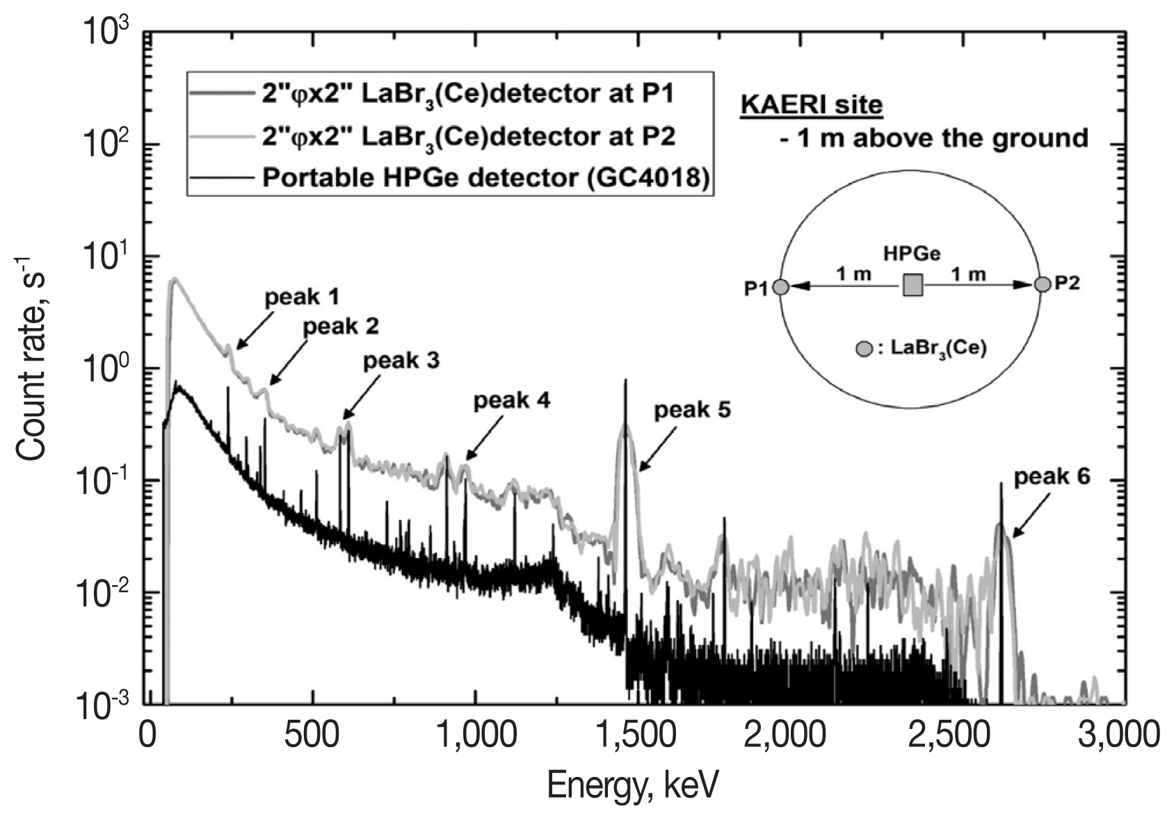
The in situ gamma-ray spectrometry was conducted on flatland at the KAERI site. For the reference of the results, a portable HPGe detector with ISOCS software was used to determine the radioactive concentration of natural radionuclides in the ground because of this well-known and widely-used method. Two measurements using the 2ŌĆ│ŽĢ├Ś2.0ŌĆ│ LaBr3(Ce) detector were then made 1 m beside the HPGe detector, left (P1) and right (P2), at the same site. The height of both detectors was set at 1 m above the ground, and the counting time at the position was 1,800 and 3,600 seconds for the LaBr3(Ce) and the HPGe detector, respectively. The measured energy spectra for the count rate are shown in Figure 8, represented by a black line for the HPGe detector and a dark and light gray line for the 2ŌĆ│ŽĢ├Ś2.0ŌĆ│ LaBr3(Ce) detector. The energy spectra of the LaBr3(Ce) detector were displayed after the intrinsic background subtraction, according to the developed subtraction algorithm. In the case of the HPGe detector with a high energy resolution, prominent gamma-ray peaks due to natural radionuclides were well identified. Several gamma-ray peaks of natural radionuclides in the energy spectra using the LaBr3(Ce) detector were well matched in the same energy position as that of the HPGe detector.
1) Net count rate induced from a gamma-ray
Six gamma-ray peaks in the energy spectrum using the LaBr3(Ce) detector were selected to analyze the natural radionuclides. Table 3 shows an example of the calculated net count rate in peaks and the information of major gamma-rays in a peak for the energy spectrum measured at P1. Owing to the limitation of the energy resolution of the LaBr3(Ce) detector used, only peaks 5 and 6 are a singlet induced from one gamma-ray, and the others are multiplets contributed by more than two gamma-rays. According to Equation 3, the radioactivity of 40K and 208Tl can be directly calculated from the net count rate in peaks 5 and 6, respectively, by applying their in-situ calibration factors for major gamma-ray energies in peaks and their emission probabilities.
In the case of other natural radionuclides, interference correction was applied to separate the contribution of a major gamma-ray to be analyzed in a multiplet, such as that of 239 keV of 212Pb, 352 keV of 214Pb, 609 keV of 214Bi, 969 keV of 228Ac in peaks 1, 2, 3, and 4, in that order. First, the net count rate induced from a gamma-ray of 583 keV of 208Tl in peak 3 was calculated from the result of peak 6, as shown in Equation 9. Therefore, the net count rate induced from a gamma-ray of 609 keV of 214Bi was then determined by subtracting the component of 583 keV of 208Tl in the multiplet, as shown in Equation 10. Second, the net count rate of 969 keV of 228Ac in peak 4 was simply calculated by assuming the same in situ calibration factor between two gamma-rays, as shown in Equation 11. Third, the net count rate of 352 keV of 214Pb in peak 2 was calculated by subtracting the component of 228Ac with the same method. The result was then used to calculate the component of 242 keV in peak 1, and finally the net count rate of 239 keV of 212Pb was determined by subtracting the contribution of 214Pb. The last column of Table 3 shows the net count rate by gamma-ray in peaks.
where, ╔ø and ╬│ are the in situ calibration factor and emission probability of a gamma-ray, and numbers in parentheses are the energy of gamma-rays in the unit of keV, except for nŌĆ▓ (peak 3) and nŌĆ▓ (peak 4), which are the net count rate of peaks 3 and 4, respectively.
2) The natural radioactivity and its comparison
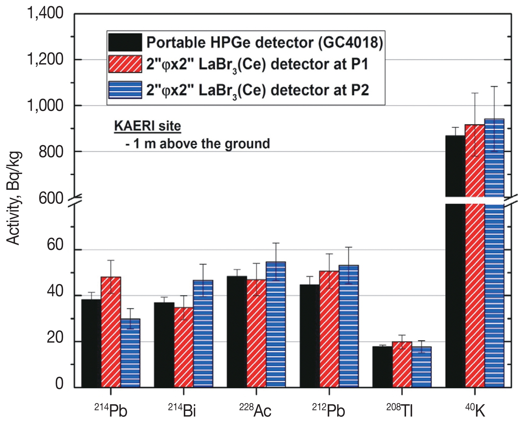
From the measured net count rate and in-situ calibration factor of the 2ŌĆ│ŽĢ├Ś2.0ŌĆ│ LaBr3(Ce) detector used, the radioactivity concentration of natural radionuclides in the ground was determined according to Equation 3. In addition, the energy spectrum using a portable HPGe detector, as shown in Figure 8, was analyzed using ISOCS software to calculate its counting efficiency at a given geometry and to determine the radioactivity of natural radionuclides. The reference value of the radioactivity to verify the results of the LaBr3(Ce) detector was considered as that from the HPGe detector with ISOCS software. That was 38.2┬▒3.3 Bq┬ĘkgŌłÆ1 for 214Pb, and 36.9┬▒2.4 Bq┬ĘkgŌłÆ1 for 214Bi in uranium decay series, 48.3┬▒3.0, 44.7┬▒3.7, and 17.7┬▒0.7 Bq┬ĘkgŌłÆ1 for 228Ac, 212Pb, and 208Tl, respectively, in thorium decay series, and 867┬▒37 Bq┬ĘkgŌłÆ1 for 40K. The comparison results between the LaBr3(Ce) and the HPGe detector are shown in Figure 9. The column without a pattern refers to the results of the HPGe detector, and the columns with patterns of diagonal and horizontal lines refer to the LaBr3(Ce) detector at 1 m left and right beside the HPGe detector at the same site, respectively.
For the validation of the results of the LaBr3(Ce) detector, its accuracy compared with those of the HPGe detector was evaluated with a U-test and relative bias (RB), as shown in Equations 12 and 13. The results of the U-test should be below 2.58, which means a level of probability of 99% in order to report results without significant difference from the reference value. The bias should be below the maximum acceptable bias (MAB), which is generally 20ŌĆō30% for natural radionuclides from the IAEA analytical quality criteria [16, 17] depending on the degree of difficulty of the test. The validation results are shown in Table 4 by dividing them into two positions. In both measurements, all results of the U-test were below 1.50, and this means that the reported result using the LaBr3(Ce) detector does not significantly differ from that of the HPGe detector. In addition, all results of the relative bias were below 26.6%, meaning that reliable results can be made in the case of using an LaBr3(Ce) detector.
where, U and RB are the results of U-test and relative bias, A and u are the radioactivity and its uncertainty, and the subscript of m and r is the measurement results using the LaBr3(Ce) detector and the reference value from the HPGe detector, respectively.
3. The determination of deposited radionuclides
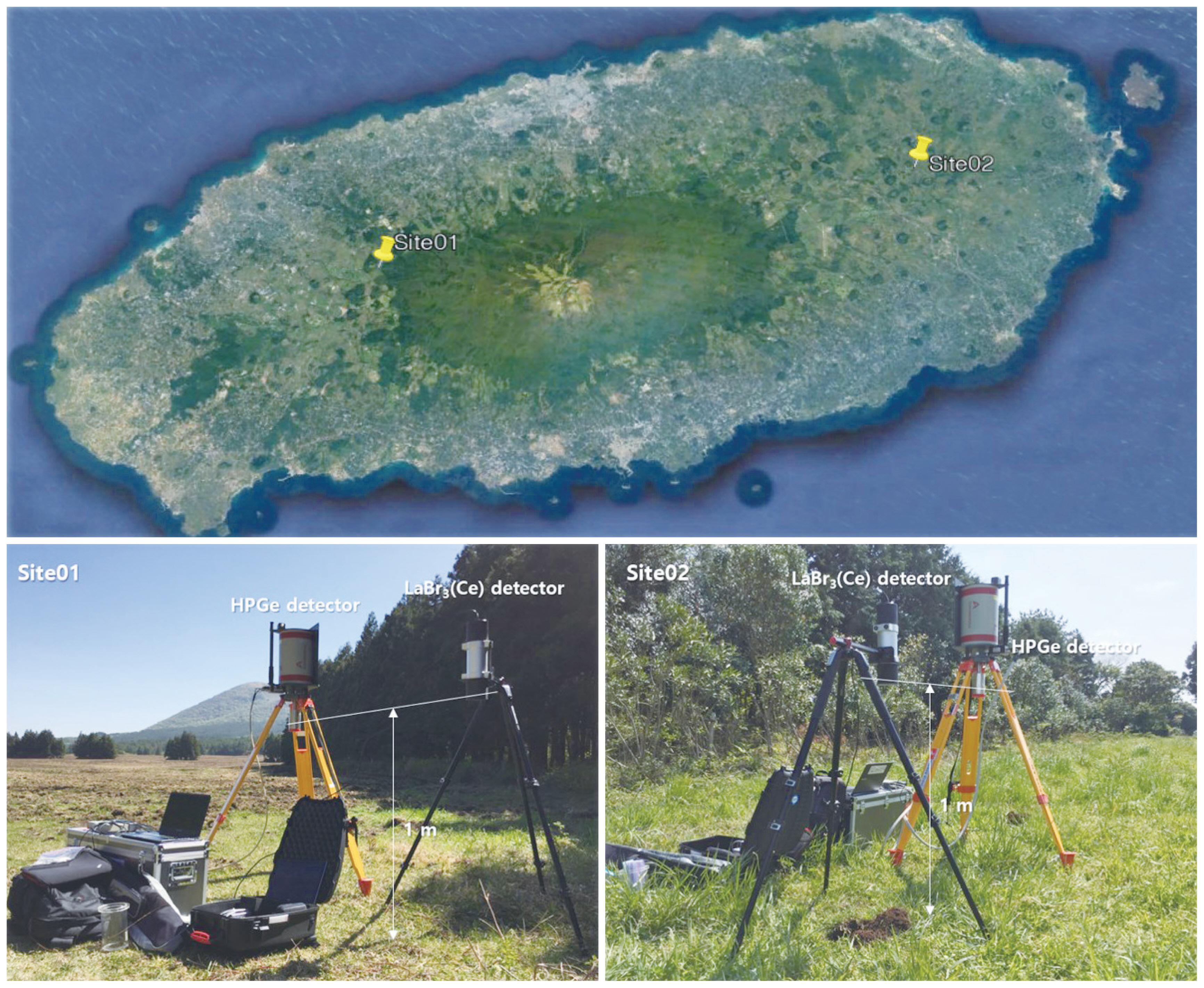
To evaluate the deposited artificial radionuclides in the ground, the in situ gamma-ray spectrometry using an LaBr3 (Ce) detector was conducted at two points on Jeju Island, as shown in Figure 10. It has been known that the radioactive fallout of 137Cs induced from past atmospheric nuclear tests is still distributed in the upper part of the ground owing to the property of volcanic ash soil and sediment. The analysis result of 137Cs in the ground using the LaBr3(Ce) detector was also compared with an HPGe detector at the same site.
1) The radioactivity of 137Cs
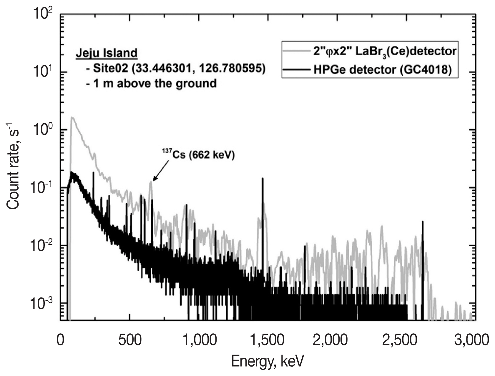
Figure 11 shows an example of measured energy spectra using the two detectors, after intrinsic background subtraction in the case of the LaBr3(Ce) detector. A gamma-ray peak of 137Cs was definitely identified in the measured energy spectrum using the LaBr3(Ce) detector at two sites. The net count rates were then calculated in a gamma-ray peak with an energy of 662 keV in the energy spectrum of both detectors. Because of no interference with other natural gamma-rays in this peak region, the calculated results directly reflect that of 137Cs. The net count rate of 137Cs at 1 m above the ground is shown in the third column of Table 5. To calculate the radioactivity from the measured net count rate, the in-situ calibration factor of a gamma-ray of 662 keV at a given geometry was applied to the calculation of Equation 3, on the assumption of superficial distribution of 137Cs in the ground.
As a result, the amount of deposited 137Cs in the ground accounted for about 201┬▒30 and 185┬▒28 Bq/m2 at both sites of Jeju Island when evaluating the results of the LaBr3(Ce) detector. With the same method, the measured net count rate of gamma-rays emanating from 137Cs using the HPGe detector was also used to calculate radioactivity concentration using ISOCS software. The comparison between the two results using the two kinds of detector is shown in the last column of Table 5, and it shows below 10% difference. Therefore, it can be concluded that in situ gamma-ray spectrometry using a 2ŌĆ│ŽĢ├Ś2.0ŌĆ│ LaBr3(Ce) detector can produce reliable and stable measurement of radioactivity in the ground, much in the same way as the already well-known HPGe detector with ISOCS software.
Conclusion
A 2ŌĆ│ŽĢ├Ś2.0ŌĆ│ LaBr3(Ce) detector was applied to in situ gamma-ray spectrometry in an environment to analyze natural radionuclides as well as radioactive cesium deposited in the ground. First, the method for the intrinsic background subtraction of an LaBr3(Ce) scintillator was developed to obtain the contributions of environmental gamma-rays in the measured energy spectrum. The in situ calibration factor of the LaBr3(Ce) detector was then calculated from MCNP simulation at a given geometry, which was 1 m above the ground due to the uniform and superficial distribution of natural and artificial radionuclides, respectively. After preparing the background subtraction and calibration factor, the in situ gamma-ray spectrometry using the LaBr3(Ce) detector was conducted to verify the analysis results of natural as well as artificial nuclides in the ground. The results were compared with those of a portable HPGe detector and ISOCS software at the same site. Good agreement between them was achieved from the validation test. This means that an LaBr3(Ce) detector can produce reliable and stable readings of radioactivity from deposited radionuclides deposited in the ground.