Introduction
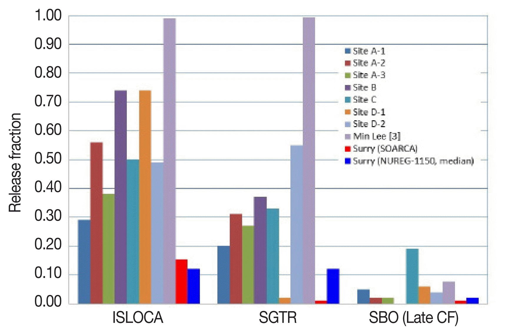
Since the Fukushima accident, the assessment of the source term to the environment has been a key concern of nuclear safety. An Interfacing-System Loss-Of-Coolant-Accident (ISLOCA) has been identified as the most hazardous accident scenario in the typical pressurized water reactors (PWRs) [1]. ISLOCA is defined as a pipeline directly connected to the reactor coolant system (RCS) is broken outside of the containment boundary [2]. According to a few of the published PSA reports [3–6], the release of CsI (cesium-iodine) as a major fission products concerned have been estimated from 30% to 99% of total core inventory during ISLOCA as shown in Figure 1.
Currently, interesting points of ISLOCA as the view of the source term to the environment are:
To improve the understanding of thermal hydraulic behaviors and relevant severe accident progress; and
To consider the effects of outside containment, for an example, effects of auxiliary building structures, on fission products behaviors.
The present study as an effort to improve the knowledge of the source term to the environment during ISLOCA focuses on an improvement of the estimation method. The improvement was performed to take into account an effect of broken pipeline and auxiliary building structures relevant to ISLOCA. An estimation of the source term to the environment was for the OPR-1000 plants by MELOCR code version 1.8.6 [7].
Materials and Methods
1. Characterizing ISLOCA
The typical Korean PWR’s PSA report [6] denoted that a potential pathway of the ISLOCA occurs in the shutdown cooling system (SCS) suction pipeline linked with a RCS’s hotleg. A potential break location is identified as the suction pipeline near the shutdown cooling, i.e., low pressure safety injection (LPSI) pumps. Under this background, a basic scenario of the ISLOCA was simulated using MELCOR 1.8.6 version.
2. MELCOR modeling
1) Plant modeling
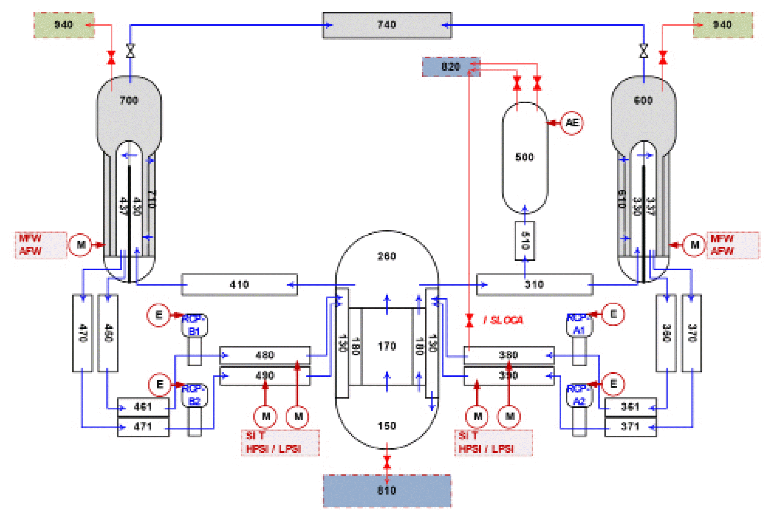
The reference plant adopted OPR-1000 type plants, which are the typical Korean PWR plants (Introduction of OPR-1000 in Wikipedia website, https://en.wikipedia.org/wiki/OPR-1000). These plants were designed for a two-loop (2 steam generators) type PWR with 2,815 MW thermal power and housing a large dry containment. The key safety features of the RCS coolant inventory makeup are four safety injection tanks (SITs), two high-pressure safety injection (HPSI) systems, and two low-pressure safety injection (LPSI) systems with a refuelling water storage tank (RWST) as a primary water source. Thermal-hydraulic (CVH package) nodalization in the MELOCR input deck for the reference plant is shown in Figure 2.
2) ISLOCA relevant modeling
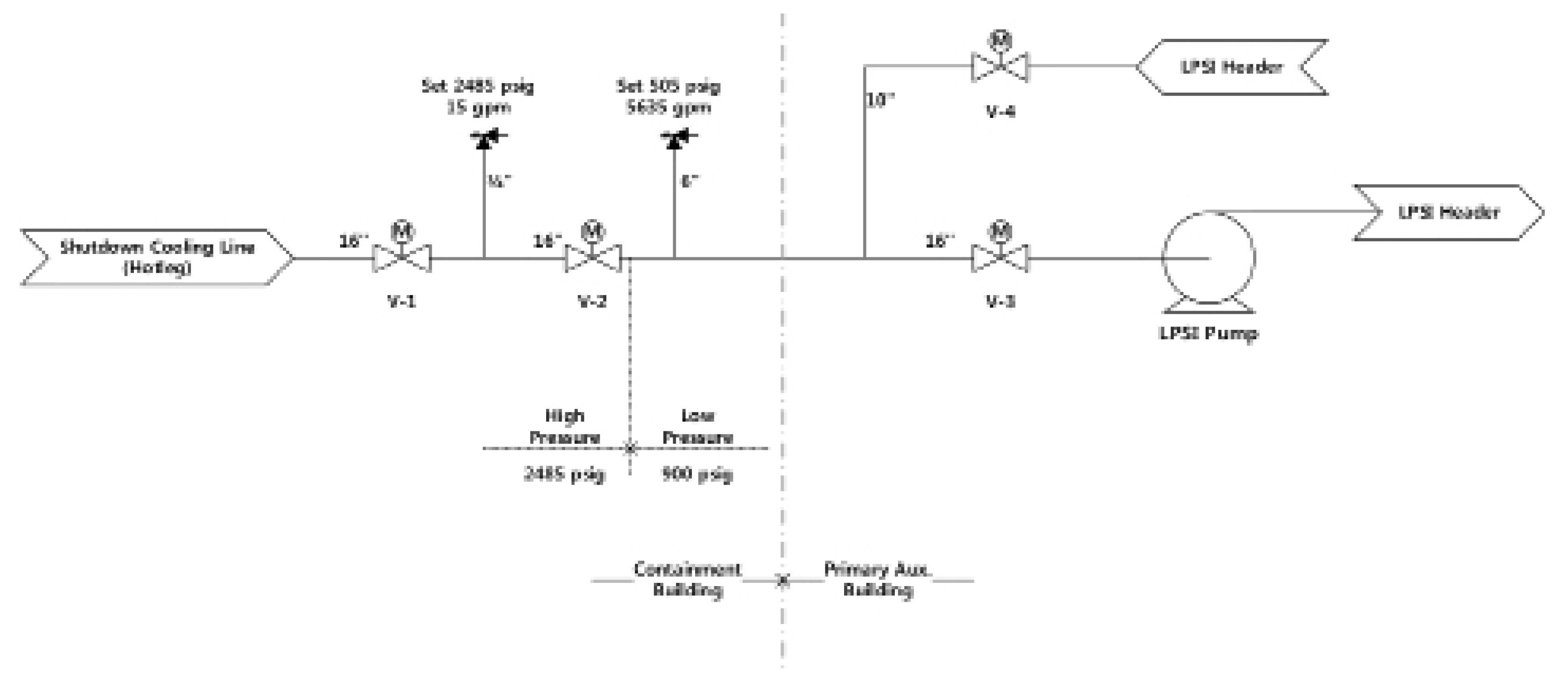
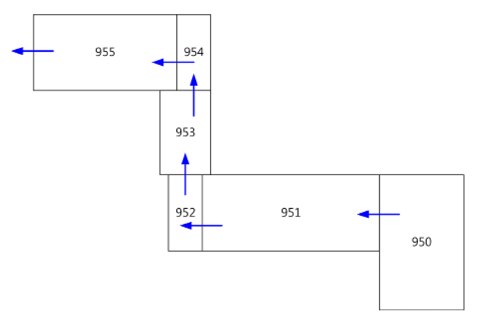
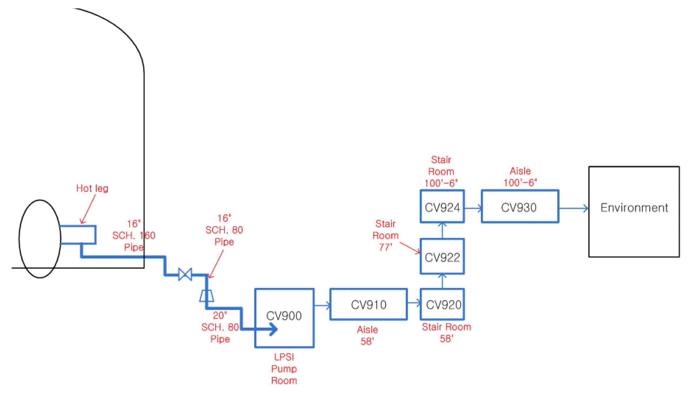
The relevant release path (broken pipeline) of ISLOCA consists of a SCS suction pipeline from the hotleg as shown in Figure 3 and the auxiliary building of the plant in Figure 4. To improve the estimation method of the ISLOCA, these pathway structures should be modeled.
The relevant SCS pipeline is about 0.25 m inner-diameter and about 100 m of pipe length with a complex configuration to connect a hotleg (0.0 m reference level) to SCS pumps (−13.8 m level).
The auxiliary building also has a complex layout to install several structures, systems, and components (SSCs). With the direct release pathway from a broken SCS pipeline to environment, it is located in a −15.3 m underground level SCS pump room with 370 m3, −12.0 m underground level aisle with a 1,090 m3 stair area from the aisle to the ground level aisle with the 140 m3, and 0.9 m ground level aisle with the 2,200 m3 involved in an environmental contact door (2.0 m× 2.1 m dimension). Connecting points between auxiliary building compartments shown in Figure 4 are installed at three fire protection doors (one in the pump room 1.0 m×2.1 m, and the others are 2.0 m×2.1 m).
The relevant release pathway of the selected ISLOCA scenario is delineated in Figure 5.
3) ISLOCA scenario
The ISLOCA transients are varied by the break size, the availability of the safety features, and operator actions. The present study was to obtain basic features of the fission products release to the environment. The worst and critical scenario was selected.
The selected break size is 0.25 m inner diameter of pipeline, 0.048169 m2 cross-sectional area. The availability of the safety injections is minimized as only four safety injection tanks (SITs) with a total of 200 tons of water reserved. The operator action does not consider. Table 1 shows the key features of the selected ISLOCA scenario.
Results and Discussion
The accident progression of the selected ISLOCA scenarios is shown in Table 2. In the simulation, a break in the SCS pump suction line occurs at 0.0 second. The reactor is tripped at 20 seconds with secondary steam line isolation. The main feedwater stopped and the auxiliary feedwater is no operation. Because of the break flow of coolant to the SCS line, the safety injection tanks (SITs) are injected from 90 seconds to 250 seconds. Core degradation starts at 2,149 seconds. Consequently, core uncovered. Gap release of fission products starts from 2,510 seconds. UO2 molten fuel to the lower head relocates at 6,161 seconds and debris quench starts at 7,954 seconds. A vessel breach occurs at 8,510 seconds after the core support plate failure (8,363 seconds).
It is believed that the accident progression in this simulation is dominantly affected from the break size (0.25 m diameter), minimum operation of the safety feature (only SITs operation), and lack of inventory reservation function of the containment. Fission products behaviors in the release pathway are inferred indirectly from key thermal hydraulic behaviors of RCS, core, broken pipeline and auxiliary building as shown in section 3.1.
1. Plant transient behavior
1) RCS and core
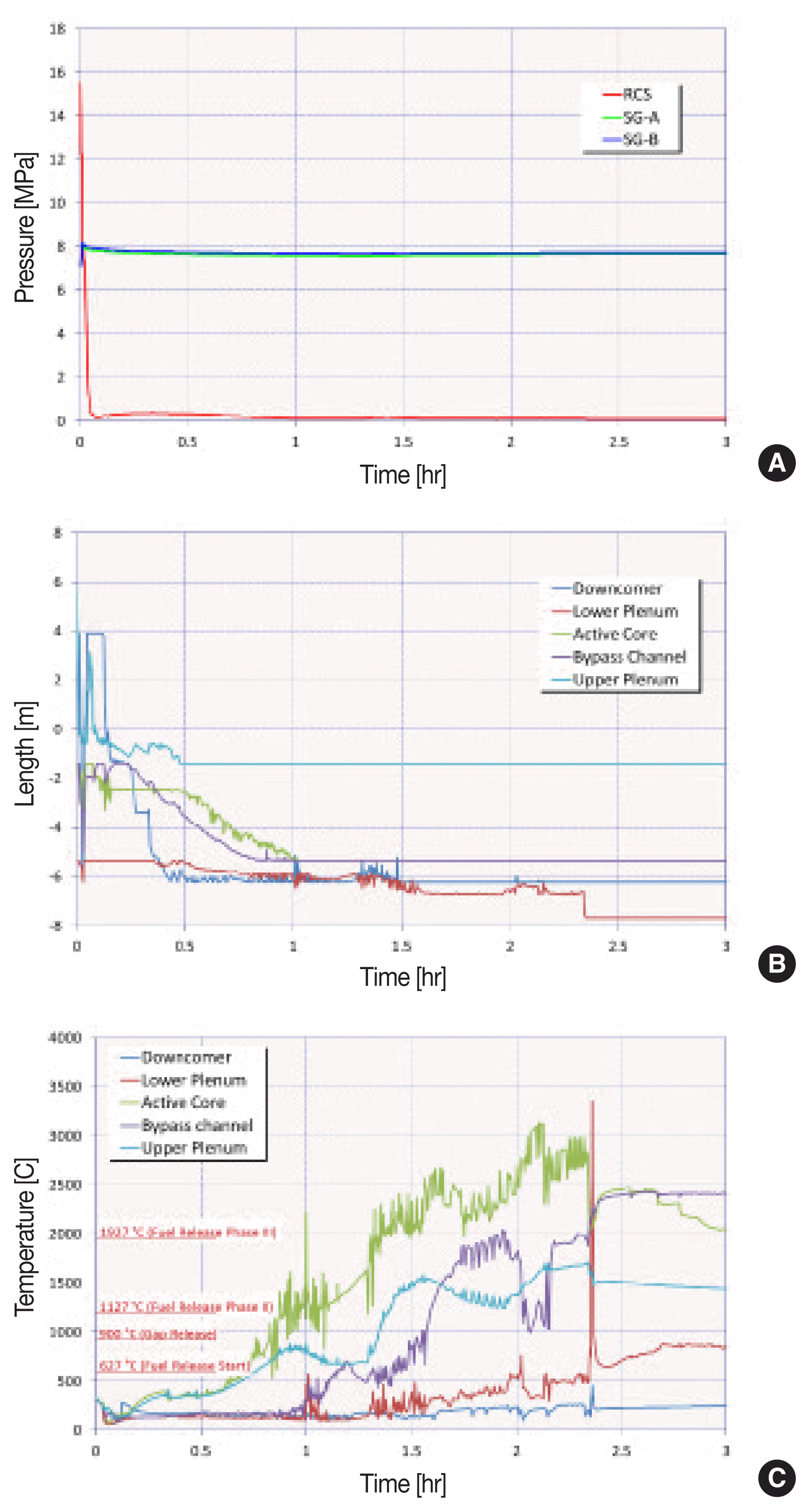
The plant transient behavior shows similar features of a typical LOCA transient in PWR except the reservation of the loss-coolant in the containment (Figure 6). Figure 6A delineates the pressure of the RCS and secondary-side of the steam generators. Because of no reservation of leak coolant in the containment, the RCS pressure rapidly goes down to the environmental pressure. The secondary-side is not functioned for heat removal as typical LOCA scenarios.
The reactor core water level decreases after SIT injection periods (90 seconds to 250 seconds) (Figure 6B). The core region develops an uncovered water level from 2,149 seconds except for a few fluctuations during the early period and dries out after about 4,000 seconds.
The temperatures of the major parts of the reactor increase from the core region uncovered (2,149 seconds) according to a decrease in the water level, and finally reach the core degradation temperature (Figure 6C). The core heat up progresses until a vessel breach occurs (8,510 seconds).
2) Break line
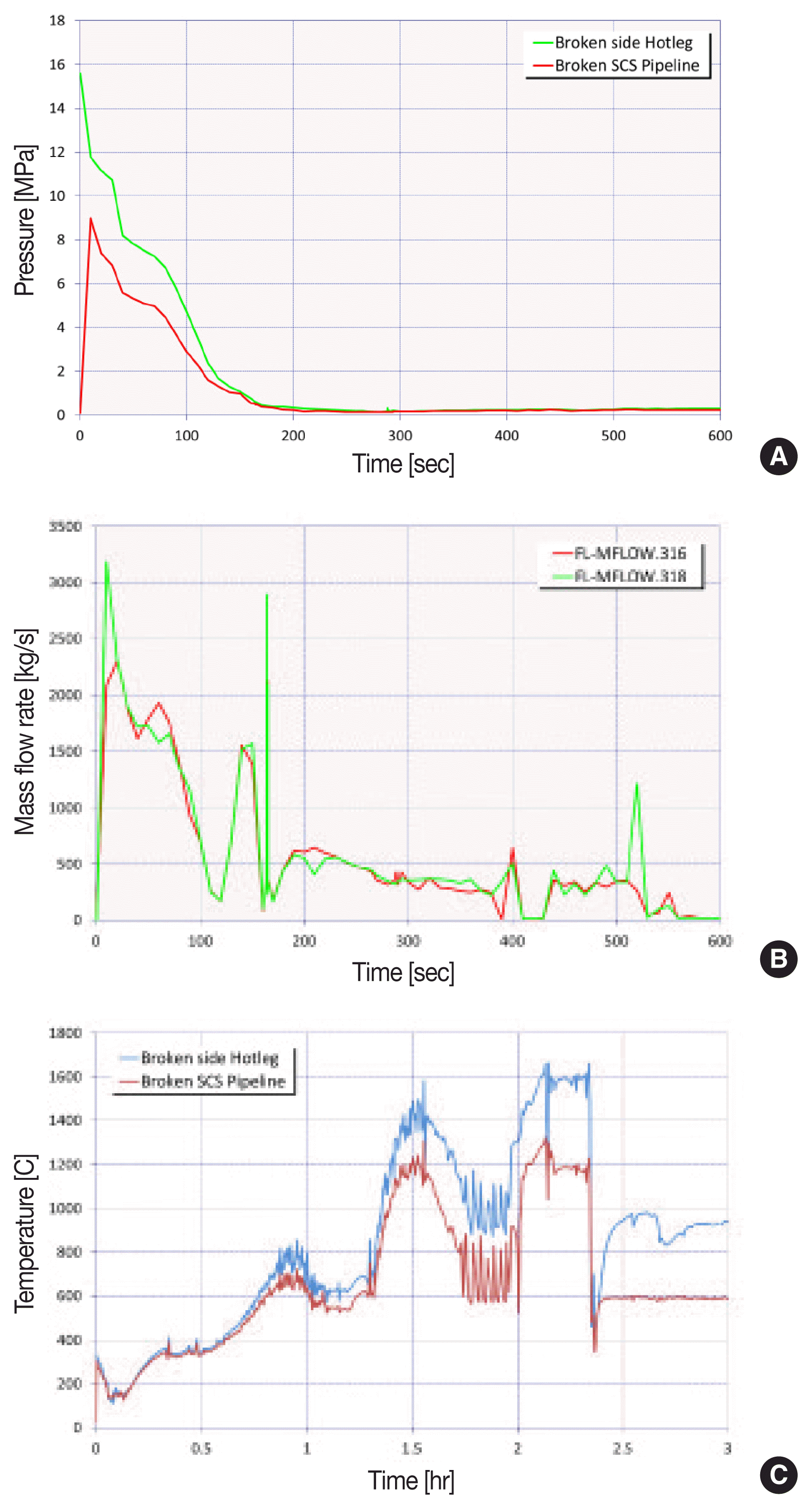
The pressure of the SCS pump suction line which induces the break flow is shown in Figure 7A. The pressure difference between the broken hotleg and break line reduces during the early period (0 to 200 seconds).
The break line forms a break flow through the SCS pipeline. In this simulation, it reaches a peak flow rate of 2,500 kg sec−1 where a near break occurs, and rapidly reduces the minimum flow rate from about 0 second to 600 seconds (Figure 7B). This result shows that the simulated break flow is similar to a typical large break LOCA except the effect of containment pressure response as a background pressure of the break flow.
The temperature in the broken-side hotleg continuously increases according to the progression of the core degradation (Figure 7C). Note here that the hotleg temperature reached 1,650°C slightly before the vessel failure time (about 8,200 seconds).
3) Auxiliary building
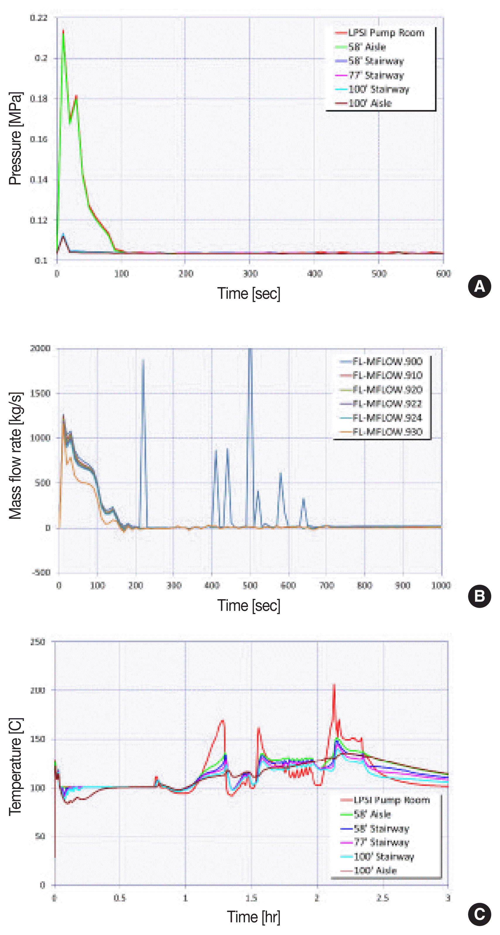
An auxiliary building is the primary concern in view of characterizing the fission products behavior. Figure 8 shows the key thermal hydraulic features in an auxiliary building during the simulated ISLOCA.
Induced pressures owing to ISLOCA are shown in Figure 8A. The pressures slightly build up in the broken room (i.e., pump room and near aisle) during 100 seconds, and soon after, it approaches the environmental atmosphere pressure. The break flow is concentrated on during an early period (600 seconds) of ISLOCA and a flow limited during late long period (Figure 8B).
The temperature distributions in an auxiliary building show an interesting point of ISLOCA transient (Figure 8C). All nodes of the auxiliary building lay on hot temperatures to be approached by plant workers. Particularly, the pump room and near aisle vapor temperatures reach above 800°C and 300°C, respectively. The liquid maintained a saturated temperature (about 100°C) of 1.0 atmosphere.
This result shows that fission products, particularly volatile materials, will be continuous released into the environment as vapor or aerosols, and thus the auxiliary building circumstances will act unfavorably to mitigating the release of the fission products.
2. Source term
As the major concern of the present study, the fission products features are shown in Figures 9 and 10. First, the major release mechanisms of the fission products from the reactor core are related with the progression of a severe accident. In particular, core degradation mechanisms govern the primary release of the fission products. Their transports through the several compartments of the plant are related with the final environmental release.
Figure 9A shows the key features of the core degradation. The core degradation materials consist of UO2, Zr, and stainless steel. 7.7 tons of zirconium is oxidized during this period. After core degradation, 122 tons of molten-core materials are ejected into the containment cavity at the occurrence of a vessel breach.
During this core degradation, vapors or aerosols of fission products are generated. In Figure 9B, the difference of power (about 20 MW) between the core decay power (DCH-COREPOW) and actual core power rate (COR-EFPD-RAT) represent the amount of fission products to leave from the core region to other compartments. Meanwhile, fission products transport on the ISLOCA release pathway is almost blocked by the vessel breach, because the material source of the release pathway of ISLOCA, i.e., the core materials in the vessel, are removed by the vessel breach, as shown in the red line in Figure 9B.
Figure 9C shows the core-ring 1 region fuel temperatures, which are related with the release of fission products from fuel to the near circumstance. Fission products are released by the fuel temperature and duration. From Figure 9C, about 6,000 seconds almost fuel regions (from 104 to 113) are heated up, which results in a large release of the source term from the fuel.
Figure 10 shows the fission products release distribution in the plant, i.e., the reactor coolant system, containment, auxiliary building, and environment.
In Figure 10A, most of the cesium-iodine (CsI) group is released from the fuel during core degradation until a vessel breach. Around a vessel breach, 40% of CsI is released into the environment, 27% remains in RCS, and 26% remains in an auxiliary building.
In Figure 10B, most of the Cs group is released from the fuel at a similar time as CsI. 33% of Cs releases into the environment, 37% remains in RCS, and 21% remains in an auxiliary building.
Environment release fractions of all fission products groups shows in Figure 10C. Most of releases are concentrated on an early phase (2–4 hours). Severity of ISLOCA to the consequential effect is due to this release aspect of fission product.
After the vessel breach, 120 tons of molten core materials are ejected into the cavity. These ejected materials are involved in molten-core-concrete-interaction (MCCI) in the cavity during a late long-term period. This reaction contributes to the long-term behaviors of the source term, but adds limited amounts compared with the core degradation period in the current ISLOCA.
Note here that the current simulation did not consider the deposition or scrubbing of the fission products, and thus the release fractions of CsI and Cs reach 40% and 33% of the total inventories, respectively.
Conclusion
As an effort to improve the estimation method of source term to the environment for the ISLOCA, the relevant models of release pathway, i.e., broken pipeline and auxiliary building have been improved. An ISLOCA scenario associated with the improved features has been examined by the MELCOR code 1.8.6 version. The simulation results show that the environmental release of the fission products occurs from the start of the core degradation to the vessel breach, and meanwhile the release fractions of CsI and Cs reach 40% and 33% of the total core inventories, respectively. Note here that the plant and auxiliary building behaviors in the simulation provide useful insight to characterize the ISLOCA behaviors. These will be the basic knowledge of source term to the environment due to an ISLOCA. Further study is recommended to obtain an improved technical basis of the fission products behaviors during an ISLOCA.


