AbstractBackgroundThe conventional cerium-doped Gd2Al2Ga3O12 (GAGG(Ce)) scintillator-based gamma-ray imager has a bulky detector, which can lead to incorrect positioning of the gamma-ray source if the shielding against background radiation is not appropriately designed. In addition, portability is important in complex environments such as inside nuclear power plants, yet existing gamma-ray imager based on a tungsten mask tends to be weighty and therefore difficult to handle. Motivated by the need to develop a system that is not sensitive to background radiation and is portable, we changed the material of the scintillator and the coded aperture.
Materials and MethodsThe existing GAGG(Ce) was replaced with Bi4Ge3O12 (BGO), a scintillator with high gamma-ray detection efficiency but low energy resolution, and replaced the tungsten (W) used in the existing coded aperture with lead (Pb). Each BGO scintillator is pixelated with 144 elements (12×12), and each pixel has an area of 4 mm × 4 mm and the scintillator thickness ranges from 5 to 20 mm (5, 10, and 20 mm). A coded aperture consisting of Pb with a thickness of 20 mm was applied to the BGO scintillators of all thicknesses.
Results and DiscussionSpectroscopic characterization, imaging performance, and image quality evaluation revealed the 10 mm-thick BGO scintillators enabled the portable gamma-ray imager to deliver optimal performance. Although its performance is slightly inferior to that of existing GAGG(Ce)-based gamma-ray imager, the results confirmed that the manufacturing cost and the system’s overall weight can be reduced.
ConclusionDespite the spectral characteristics, imaging system performance, and image quality is slightly lower than that of GAGG(Ce), the results show that BGO scintillators are preferable for gamma-ray imaging systems in terms of cost and ease of deployment, and the proposed design is well worth applying to systems intended for use in areas that do not require high precision.
IntroductionAccording to the International Atomic Energy Agency, 442 nuclear power plants were in operation worldwide as of March 2020, of which 296 were more than 30 years old, accounting for 66.9% of the total [1]. As the entire population of nuclear power plants ages and individually reaches the end of their operating life, research on the decontamination and decommissioning of nuclear power plants is underway. The two most important problems in decontamination, decommissioning, and demolition of waste classification are (1) nuclide identification and (2) accurate identification of the location of radioactive materials [2]. Furthermore, the capabilities to localize and identify radioactive materials are useful in environmental monitoring because monitoring demolition sites is expected to continue after a nuclear power plant has been decommissioned [3].
As a result, many research groups have successfully developed gamma-ray imaging systems that can detect the presence of radioactive materials. However, weighty equipment can make it difficult to effectively find hot spots contaminated with radioactive materials because the primary system of nuclear power plants has many pipes and pumps located in narrow spaces. Hence, reduction of the weight of the equipment to facilitate portability is an essential requirement.
Gamma-ray imagers are divided into two main categories, depending on the way in which the source image is obtained: Compton cameras and coded aperture-based imagers [4]. Typical Compton cameras include Polaris-H (H3D Inc., Ann Arbor, MI, USA) and HEMI (Lawrence Berkeley National Laboratory [LBNL]) whereas coded aperture-based gamma-ray imagers include iPIX (Mirion Technologies Inc., Atlanta, GA, USA) and HiSpect (CEA, Cedex, France) [5–8]. We developed a coded aperture-based gamma-ray imager named Epsilon-G (Energetic Particle Sensor for the Identification and Localization of Originating Nuclei-Gamma) and details of this design were reported previously [9].
The size and weight of Epsilon-G are 104 mm×144 mm× 197 mm and 5.7 kg, which exceed those of other gamma-ray imagers. Specifically, the aforementioned gamma-ray imagers weigh 4 kg (Polaris-H), 4 kg (HEMI), 2.5 kg (iPIX), and 3 kg (HiSpect), respectively. Because the Epsilon-G is designed to detect gamma rays in the energy range between 40 keV and 3 MeV, it uses a thick (2 cm) and dense coded aperture consisting of tungsten (W) with a purity of 99.5% and a density of 19.3 g/cm3 including a side shield encompassing the detector module for the detector module (scintillator and silicon photomultiplier [SiPM] array), which account for the bulk of the weight of the system. This prompted us to use a low-density material such as lead (Pb) instead of W to fabricate the coded aperture to minimize the total weight of the system.
Considering the high gamma-ray response efficiency and low-price competitiveness of bismuth germanate (BGO), we decided to evaluate the applicability of the imager by lowering the weight by replacing Cerium doped Gadolinium Aluminium Gallium Garnet, or GAGG(Ce), and changing the detector shielding structure. Many scintillators, such as NaI(Tl), CeBr3, SrI2(Eu), LaBr3(Ce), and LaCl3(Ce), have good energy resolution, but are particularly hygroscopic and the design is particularly difficult to pixelate, with low density and effective mass [10]. On the other hand, BGO has a lower photon yield than the GAGG(Ce) scintillator, but is neither hygroscopic nor does it have high density; thus, it can withstand a thinner active layer than GAGG(Ce) for imaging applications that do not rely on fine energy resolution for radioisotope identification. By reducing the thickness of the scintillator, the shield thickness of the coded opening side may be reduced accordingly, thereby reducing the weight and volume of the entire system.
In this study, we examined the spectral performance—energy resolution, peak-to-Compton ratio (PCR), and peak-to-valley ratio (PVR); the performance of the gamma-ray imaging system—angular resolution, field of view (FOV), and image sensitivity (IS); and the image quality—peak signal-to-noise ratio (PSNR), normalized mean square error (NMSE), and structure similarity (SSIM); while also determining the optimal scintillator thickness for the gamma-ray imaging system.
Materials and Methods1. Epsilon-GA SiPM has several features that improve the usability and robustness compared to conventional photomultiplier tubes (PMTs). It is capable of low-voltage operation (less than 50 V) and is insensitive to magnetic fields. The photodetection efficiency (PDE) of SiPM is generally higher than that of PMT, and the maximum PDE for recent SiPMs or multi-pixel photon counters (MPPCs) is approximately 50%, including the fill-factor loss [12]. Based on these characteristics, Epsilon-G, a coded aperture-based gamma-ray imager with pixelated GAGG(Ce) detector modules coupled to SiPM array, was developed [13]. The SiPM array (ArrayC-30035-144P; Semiconductor Components Industries, Phoenix, AZ, USA) used for Epsilon-G features high gain, low operating voltage, temperature stability, high output uniformity, and excellent single photon sensitivity at wavelengths ranging from ultraviolet to visible [14]. In addition, the GAGG(Ce) detector (Epic-Crystal Ltd., Kunshan, China) has high photon yield, fast decay time, excellent radiation resistance, and can be used under high-capacity conditions. As shown in Fig. 1, both SiPM and GAGG(Ce) arrays were pixelated into 12×12 elements, and the pixel sizes of SiPM and GAGG(Ce) were 3 mm×3 mm and 4 mm×4 mm, respectively. The pixel pitch of the scintillator and the SiPM array is 4.2 mm, and both were wrapped in Teflon tape to assist reflection and mitigate ambient light interference.
2. BGO Scintillator-Based Detector ModuleThe BGO scintillator emits green fluorescent light with a maximum peak wavelength of 480 nm and is widely used in high-energy physics, medicine, and geological research due to its high static force and proper flash efficiency [11]. As shown in Fig. 2, the BGO (Epic-Crystal, Ltd., China) is pixelated into 12×12 pixels, has a pixel pitch of 4.2 mm and a pixel area of 4 mm×4 mm, the same size as the GAGG(Ce) scintillator used in Epsilon-G. Between the respective pixels, a 0.2 mm-thick BaSO4 layer is coupled as a reflector, and the edge and bottom of the scintillator are wrapped in 0.3 mm-thick BaSO4 and aluminum foil. The BGO scintillator and SiPM array are optically coupled using an EJ-560 optical interface sheet (Eljen Technology, Sweetwater, TX, USA) and TSK-5353 optical grease (Momentive, Tokyo, Japan). The entire assembly containing the detector module was wrapped with Teflon tape. In Table 1, the scintillator characteristics of BGO are compared with those of GAGG(Ce).
3. Coded Aperture DesignA centered mosaic modified uniformly redundant arrays (MURA) pattern was used for the coded aperture mask that was employed to encode the spatial radiation-field information. A centered mosaic pattern is a method for obtaining a fully coded field-of-view (FCFOV) by copying and extending to (2p-1)×(2p-1) for the prime number (p) closest to the number of ranks of the detector [15]. The thickness of the optimal mask was determined to be 2 cm in a previous study [16] in terms of the PSNR, NMSE, full width at half maximum (FWHM), and SSIM. Therefore, in this study, a coded aperture mask that has a 21×21 mosaic MURA pattern with a thickness of 2 cm of Pb (density of 11.34 g/cm3) was used. As shown in Fig. 3, the thickness of the side shield for the detector module was manufactured differently depending on the thickness of the scintillator.
Results and Discussion1. Comparison of the Spectral Characteristic1) Energy resolutionOur previous work demonstrated that the spectral performance was excellent when the bias voltage of SiPM was 28 V, and based on this, the operating bias was set. The coded aperture mask was not used in experiments to measure the energy resolution. The activity of the source was 779.6307 kBq for 137Cs, located in the center of the FOV and 25 cm away from the detector. Since each pixel has a variable response, gain correction by pixel was performed as described before [15], and a spectrum was acquired by collecting 1,000,000 events for each different detector thickness, as shown in Fig. 4.
Fig. 4 shows the dependence of the 137Cs energy spectra on the thickness of the BGO scintillator and Table 2 compares the energy resolution (R), PCR, and PVR based on the thickness of the BGO scintillator. As indicated in the annotated information in Fig. 4, for the 10 mm-thick BGO scintillator, the resolution of the 662 keV peak was the best, and the PCR and PVR values were the highest. The change in thickness from 10 mm to 20 mm resulted in a minimal improvement in energy resolution, but the secondary escape of Compton scattering gamma rays was much higher for the 5 mm-thick BGO scintillator array, particularly for photons scattering forward after the initial interaction.
PCR and PVR measurements became less accurate as the thickness increased from 10 mm to 20 mm, although the maximum resolution decreased as the surface reflection and scintillator loss increased. To summarize, the 10 mm-thick BGO scintillator outperformed the 20 mm-thick BGO scintillator by 21%, 3.94%, and 9.81% in terms of the energy resolution, PCR, and PVR, respectively. Fig. 5, which compares the peak height for the different scintillators, shows that the relative height of the photo-peak increases as the thickness of the scintillator increases, which significantly improved the energy resolution of the BGO scintillator array with a thickness of 10 mm or more. The peak-to-total ratio refers to the proportion of the full energy peak portion of the entire set of spectral data and is used to determine the full energy peak efficiency. In terms of image sensitivity, the more the information corresponding to the full energy peak, the higher the image sensitivity of the system is. Concurrently, the larger the peak-to-total ratio of the energy spectrum, depending on the thickness of the scintillator, the higher the image sensitivity of the system becomes.
The light yield of the BGO scintillator is about 5.9 times lower than that of GAGG(Ce), requiring a readout system with a relatively large gain. In the case of BGO, a 5 mm-thick scintillator is sufficient to detect 662 keV gammas from 137Cs. As a result of the experiment, the peak channel values corresponding to 662 keV for each thickness decreased in the order of 5 mm, 10 mm, and 20 mm. However, as shown in Fig. 4, the detection efficiency of the secondary escape event increases because the capture volume increases as the scintillator thickness increases, which in turn increases PCR by reducing the Compton area across the entire spectrum. However, if the thickness of the scintillator is relatively long 20 mm, the high aspect ratio can lead to significant self-absorption due to several surface scattering events before the scintillator escapes the crystal, and the signal size can be relatively small as it is more likely to exit the used reflector to cause cross talk.
2) Comparison of spatial interaction distribution via 2D flood mapUsing the data used for spectrum collection under the same experimental conditions as in the previous experiment, a two-dimensional (2D) flood map can be obtained by varying the thickness of the scintillator as shown in Fig. 6, which shows the interaction intensity for each pixel. The localization is the best, particularly near the center of the array, for the 10 mm-thick case. In the case of the 5 mm-thick scintillator, Compton events are the prominent reaction, as the thickness is not sufficient to absorb the 662 keV gammas from 137Cs used in the experiment. Consequently, the signal-to-noise ratio (SNR) of energy information used for determining the reaction position of the radiation becomes low, and the 2D flood map becomes relatively less well-resolved. In particular, this phenomenon is more pronounced at the corners. On the other hand, in the case of the 20 mm-thick scintillator, once the pixel ratio (i.e., area-to-height ratio) of the scintillator exceeds a certain level, the light self-absorption reaction occurs inside the scintillator and the reflective efficiency of the reflector decreases. This lowers the signal intensity because of information-carrier loss due to increased scintillator-light attenuation, which affects the positional resolution. Therefore, in the case of BGO, the scintillator array with a thickness of 10 mm was determined to have the appropriate pixel ratio for improved positional resolution.
To quantify these qualitative observations, a one-dimensional (1D) sum profile representing the sum of each column or row was used, as shown in Fig. 7, which shows that the overall count intensity is scaled according to the detected volume as expected. The edge pixels are not clearly separated, particularly for the 20 mm-thick scintillator because lower energy events are more predominant in the distribution. Regardless of the scintillator thickness, the pixels are not clearly separated from the response of their nearest neighbors because of the relatively low scintillation efficiency. This is attributed to the low light yield, resulting in the poor SNR in position extraction. The SNR is larger for the 10 mm-thick scintillator for which the signals have a greater number of information carriers. Thus, the positional resolution of this scintillator is superior to that of the others.
Owing to the reduced participation of multi-pixel events in the 10 mm-thick case, the FWHM of the pixel-peak identification is the smallest relative to the baseline (bottom of the peak in the middle position). In the case of the 5 mm-thick BGO scintillator, the relatively small thickness limits the degree of light spreading to a remarkable extent, but the resolution of the peaks near the edges does not improve because of signal loss owing to Compton scattering. In addition, in the case of the BGO with a thickness of 20 mm, the signals have to travel a relatively long distance, which can cause light to be generated and spread when reaching the SiPM. Therefore, in the case of scintillators with large densities and effective Z numbers such as BGO, the light reaching the SiPM spreads as the pixel length increases, thus the relative spatial resolution decreases, particularly near the edge. Therefore, the spatial resolution of the 10 mm-thick BGO, which has an appropriate length, is the highest.
The main factor affecting the spectral performance is the use of the BGO scintillator, whereas changing the shield from tungsten to lead affects the spectral performance negligibly. The reason for changing the shield from tungsten to low-density lead is to reduce the weight of the system. The same phenomena were observed for GAGG(Ce) scintillator-based systems.
2. Comparison of Imaging System Performance1) Angular resolutionFor the image used to evaluate the performance of the imaging system, all data obtained from the equipment were used instead of using a specific energy window or only data within full energy peak. The angle at which the two sources separated and began to appear was determined as the minimum value of the angular resolution, and the separation criteria were evaluated based on the 1D profile, as shown in Fig. 8. The precision of each resolution representing the separation of the two sources is determined by the number of ranks and spatial resolution of the mask. The spatial resolution is determined by the SNR of the signal by the row/column readout technique used in the signal processing circuit, which is determined by its noise level and the photon yield of the scintillator. The extent to which each resolution affected the thickness of the BGO was investigated as follows.
To test the angular resolution of the equipment, an image acquisition test was performed by increasing the distance between the two sources until two 137Cs point sources (300.606 kBq and 304.14 kBq, respectively) could be identified separately. At this point, the source-to-detector distance (SDD) was set to 1 m and 30,000 events were registered. Images were acquired by attaching a coded aperture mask to the front of the detector module, and the maximum likelihood expectation maximization (MLEM) method was used to reconstruct the image. At this point, the MLEM iteration number was set to 100. Quantitatively, the two sources were identified and visualized when the angles formed by the two sources and detectors were 9.5°, 8°, and 8.5° for BGO scintillators with a thicknesses of 5, 10, and 20 mm, respectively. An important factor in positioning gamma-ray reactions is the energy resolution of the detector. The higher the energy resolution, the more precise the positioning, thus the angular resolution is also affected. However, the angular resolution was approximately 1.2° lower than when using a 20 mm-thick GAGG(Ce) scintillator array because the photon yield was smaller than that of a GAGG(Ce) scintillator, resulting in a lower SNR in the signal processing circuit.
2) Field-of-viewIn a gamma-ray imager, the FOV is the extent to which a source can be located by capturing a single photograph, and even gamma-ray sources at the same location require additional time to locate according to the FOV. The Compton camera does not have a limited FOV, but in the case of the coded aperture-based gamma-ray imager, the FOV is limited by the mask pattern, mask-to-detector distance, the spatial resolution of the detector, etc., owing to the structural characteristics. For this reason, the FOV is one of the performance indicators required for the gamma-ray imager, and in the case of iPIX and HiSpect mentioned earlier, the FOV is known to be 41.4°–48.8° and 35°, respectively [1].
In the FOV experiment, an image was acquired by increasing the angular deviation of the 137Cs point source that has an intensity of 604.746 kBq from the center of the scintillator. In addition, the image reconstruction condition, the number of counts recorded at each location, and the SSD were the same as in the previous angular resolution experiment. The results of the FOV experiment are shown in Fig. 9, and for the BGOs with thicknesses of 5 mm and 20 mm, the FOVs were 44.96° and 45.74° (41.4 cm and 42.2 cm at 1 m SDD), respectively, and in case of the 10 mm-thick BGO, the FOV was determined to be 49.96° (46.6 cm at 1 m SDD). In previous studies using 20 mm-thick GAGG(Ce), the FOV was 50°, and the reason for this difference is that the spatial resolution at the edge of the scintillator is lowered, as shown in Fig. 6, because of the lower energy resolution. Therefore, this shows that the spatial resolution performance must be excellent in order to maintain the own FOV of the system given.
3) Image sensitivityThe image sensitivity was defined as the minimum time taken to acquire an image at a given dose rate, and at this time, when the accuracy of positioning the source was 80% or more, it was determined as the minimum time. The image sensitivity measurements were conducted by setting the 137Cs dose rate as 0.03 μSv/h (the background dose rate was about 0.08 μSv/h). For the experimental environment, the SDD was set to 1.075 m, and the position of the source was placed at the center of the FOV. Similarly, a coded aperture mask was mounted on the front end of the imager to acquire an image, and the accuracy was confirmed by measuring the image reconstruction time ten times for each measurement while increasing the image reconstruction time by 1 second. The image reconstruction conditions were the same as those in the angular resolution measurement experiment.
The experimental results showed that the scintillator with a thickness of 5 mm needs 25 seconds for the dose rate of 0.03 μSv/h of 137Cs and requires 11 seconds with the scintillators with thicknesses of 10 mm and 20 mm, respectively. Fig. 10 shows an image of the graphical user interface (GUI) acquired using the BGO scintillator with a thickness of 10 mm. The image sensitivity was determined to vary depending on the thickness because the detection efficiency improves as the thickness of the scintillator increases. In addition, at the same dose rate, the image sensitivity did not differ significantly from that of GAGG(Ce) scintillators of the same thickness.
4) Image qualityAppropriate positioning of the source without image noise indicates the image reconstruction performance of a gamma-ray imager. In general, reconstructed radiographic images are evaluated by deriving the PSNR, NMSE, SSIM, etc. In this study, the image quality was evaluated by placing the 137Cs gamma ray source at the center of the FOV and 30,000 events were counted for the BGO of each thickness, as shown in Fig. 11. The image reconstruction conditions are the same as in the previous experiments. The results of each evaluation index of the reconstructed image are summarized in Table 3, and each index was derived as described before [19–21]. SSIM generated a reference image by computer simulation and was derived by comparing images reconstructed with data obtained experimentally. In general, the higher the PSNR, the smaller the NMSE, and the closer the value to 1, the higher the image quality of SSIM is determined to be.
The results of the image reconstruction experiments showed that the PSNR, NMSE, and SSIM results were the best for the 10 mm thickness. This is because an excessively thin scintillator decreases the probability of detecting incident gamma rays, whereas an overly thick scintillator decreases the image quality owing to count sharing between adjacent pixels, leading to noisy reconstructed images. Here, counting sharing refers to the mislocalization of pixels due to the light spread of the scintillator, which is the result of inaccurate positioning because of poor energy resolution. Ultimately, this means that the pixels become difficult to distinguish, as shown in Fig. 6C. If the pixels are not clearly separated and unclear data are used when creating the detector map, the probability of mislocalization increases when the image is reconstructed. Table 3 compares the image evaluation parameters of the BGO scintillators with different thicknesses with those of conventional GAGG(Ce) scintillator arrays.
ConclusionThe study reported in this paper was conducted to reduce the cost and weight of the existing Epsilon-G consisting of a gamma-ray sensor, a coded-aperture mask composed of W, and a data acquisition (DAQ) system, which is a combination of GAGG(Ce) and SiPM array. We replaced the mask material from W to Pb and scintillator medium from GAGG(Ce) with BGO, and selected the thickness of BGO to be used in the system. The performance of the detector was evaluated by comparing the spectral characteristics (energy resolution, 2D flood map and 1D row-sum profile) and imaging system performance (angular resolution, FOV, image sensitivity, and image quality) for BGO scintillators with three different thicknesses. The comparison of the spectral characteristics showed the energy resolution and spatial resolution were the highest for the 10 mm-thick scintillator. Finally, we confirmed that the image quality of the reconstructed images obtained with the system using the 10 mm-thick BGO scintillator was superior to that obtained with the other two BGO scintillators. Therefore, it was determined that the optimal BGO thickness for our system was 10 mm. In addition, the weight of the entire system with the Pb mask applied to the 10 mm-thick BGO was 4.6 kg, a reduction of approximately 20% compared to the existing GAGG(Ce) and W mask (5.7 kg). Compared with the results of previous studies of the GAGG(Ce) scintillator-based Epsilon-G, the system using the BGO scintillator with a thickness of 10 mm has energy resolution of 12.81%, angular resolution of 8°, FOV of 50°, and image sensitivity of 11 seconds at a dose rate of 0.03 μSv/h for 137Cs. This explains the poor photon yield of BGO relative to GAGG(Ce). However, considering the excellent affordability of BGO, we confirmed that it is well worth applying to systems intended for use in areas that do not require high precision.
AcknowledgementsThis work is supported by Nuclear Safety Research Program through the Korea Foundation of Nuclear Safety (KoFONS) using the financial resource granted by the Nuclear Safety and Security Commission (NSSC) of the Republic of Korea (No. 2204019).
NotesEthical Statement This article does not contain any studies with human participants or animals performed by any of the authors. Author Contribution Conceptualization: Park S, Jeong M. Methodology: Park S. Jeong M. Formal analysis: Park S, Jeong M. Funding acquisition: Jeong M. Project administration: Jeong M. Visualization: Park S, Jeong M. Writing - original draft: Park S. Jeong M. Writing - review and editing: Hammig MD, Jeong M. Approval of final manuscript: all authors. References1. International Atomic Energy Agency. PRIS Power Reactor Information System: age distribution [Internet]. Vienna, Austria, International Atomic Energy Agency; 2020 [cited 2022 Dec 20]. Available from: https://pris.iaea.org/pris/worldstatistics/operationalbyage.aspx
2. Mladenov A, Stankov D, Nonova T, Krezhov K. Radiation protection, radioactive waste management and site monitoring at the nuclear scientific experimental and educational centre IRT-Sofia at INRNE-BAS. Radiat Prot Dosimetry. 2014;162(1–2):176-181.
3. Ziock KP, Collins JW, Fabris L, Gallagher S, Horn BK, Lanza RC, et al. Source-search sensitivity of a large-area, coded-aperture, gamma-ray imager. IEEE Trans Nucl Sci. 2006;3(3):1614-1621.
4. Cieslak MJ, Gamage KA, Glover R. Coded-aperture imaging systems: past, present and future development: a review. Radiat Meas. 2016;92:59-71.
5. Wahl CG, Kaye WR, Wang W, Zhang F, Jaworski JM, King A, et al. The Polaris-H imaging spectrometer. Nucl Instrum Methods Phys Res A. 2015;784:377-381.
6. Vetter K, Barnowksi R, Haefner A, Joshi TH, Pavlovsky R, Quiter BJ. Gamma-ray imaging for nuclear security and safety: towards 3-D gamma-ray vision. Nucl Instrum Methods Phys Res A. 2018;878:159-168.
7. Amgarou K, Paradiso V, Patoz A, Bonnet F, Handley J, Couturier P, et al. A comprehensive experimental characterization of the iPIX gamma imager. J Instrum. 2016;11(08):P08012.
8. Montemont G, Bohuslav P, Dubosq J, Feret B, Monnet O, Oehling O, et al. NuVISION: a portable multimode gamma camera based on HiSPECT imaging module. Atlanta, GA: Proceedings of 2017 IEEE Nuclear Science Symposium and Medical Imaging Conference (NSS/MIC). 2017 Oct 21–28. Atlanta GA. 1-3.
9. International Atomic Energy Agency. 2016 Technology Demonstration Workshop (TDW) on gamma imaging-external [Internet]. Vienne, Austria, International Atomic Energy Agency; 2017 [cited 2022 Dec 20]. Available from: https://phdsco.com/wp-content/uploads/2020/04/2016_Technology_Demonstration_Workshop_TDW_on_Gamma_Imaging-External.pdf
10. Jeong M, Van B, Wells BT, Lawrence JD, Hammig MD. Comparison between pixelated scintillators: CsI(Tl), LaCl3(Ce) and LYSO(Ce) when coupled to a silicon photomultipliers array. Nucl Instrum Methods Phys Res A. 2018;893:75-83.
11. Epic-Crystal. BGO scintillator [Internet]. Kunshan, China, Epic-Crystal Ltd; 2021 [cited 2022 Dec 20]. Available from: https://www.epic-crystal.com/download-center/index_2.html
12. Joshi S. Coded aperture imaging applied to pixelated CdZnTe detectors [dissertation]. Ann Arbor, MI, University of Michigan. 2014.
13. Jeong M, Hammig MD. Comparison of gamma ray localization using system matrixes obtained by either MCNP simulations or ray-driven calculations for a coded-aperture imaging system. Nucl Instrum Methods Phys Res A. 2020;954:161353.
14. Semiconductor Components Industries. Silicon potomultipliers (SiPM) [Internet]. Phoenix, AZ, Semiconductor Components Industries; 2021 [cited 2022 Dec 20]. Available from: https://www.onsemi.com/products/sensors/photodetectors-sipm-spad/silicon-photomultipliers-sipm
15. Jeong M, Van B, Wells BT, D’Aries LJ, Hammig MD. Scalable gamma-ray camera for wide-area search based on silicon photomultipliers array. Rev Sci Instrum. 2018;89(3):033106.
16. Park S, Boo J, Hammig M, Jeong M. Impact of aperture-thickness on the real-time imaging characteristics of coded-aperture gamma cameras. Nuclear Engineering and Technology. 2021;53(4):1266-1276.
17. Yoshino M. Study on a novel Compton-PET hybrid camera using newly developed scintillators for simultaneous imaging of PET/SPECT application [dissertation]. Sendai, Japan, Tohoku University. 2018.
18. Jeong M, Hammig M. Development of hand-held coded-aperture gamma ray imaging system based on GAGG (Ce) scintillator coupled with SiPM array. Nucl Eng Technol. 2020;52(11):2572-2580.
19. Yan Y, Cao W, Li S. Block-based adaptive image watermarking scheme using just noticeable difference. Proceedings of 2009 IEEE International Workshop on Imaging Systems and Techniques. 2009 May 11–12. Shenzhen, China. 377-380.
Fig. 1(A) Epsilon-G, (B) 12×12 pixelated SiPM array, and (C) 12×12 pixelated GAGG(Ce) scintillator array. SiPM, silicon photomultiplier. 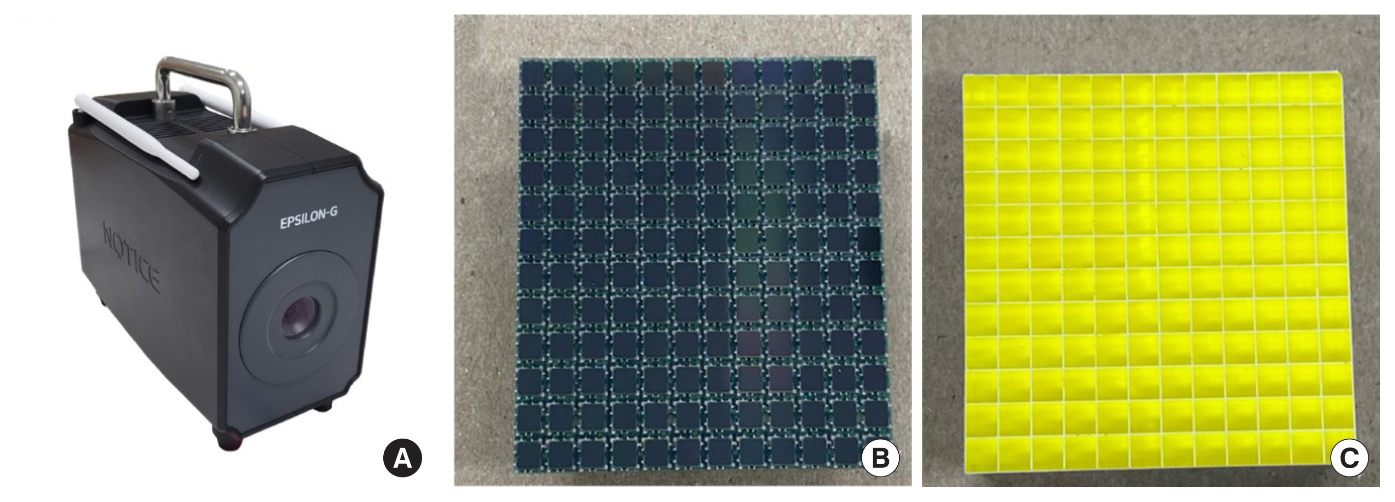
Fig. 2(Top) 12×12 pixelated BGO scintillators. The dimensions of each BGO are: (A) 50.8 mm×50.8 mm×5 mm, (B) 50.8 mm×50.8 mm× 10 mm, and (C) 50.8 mm×50.8 mm×20 mm. (D) Configuration of the detector including the scintillator, reflective index matching material, and SiPM arrays. BGO, bismuth germanate; SiPM, silicon photomultiplier. 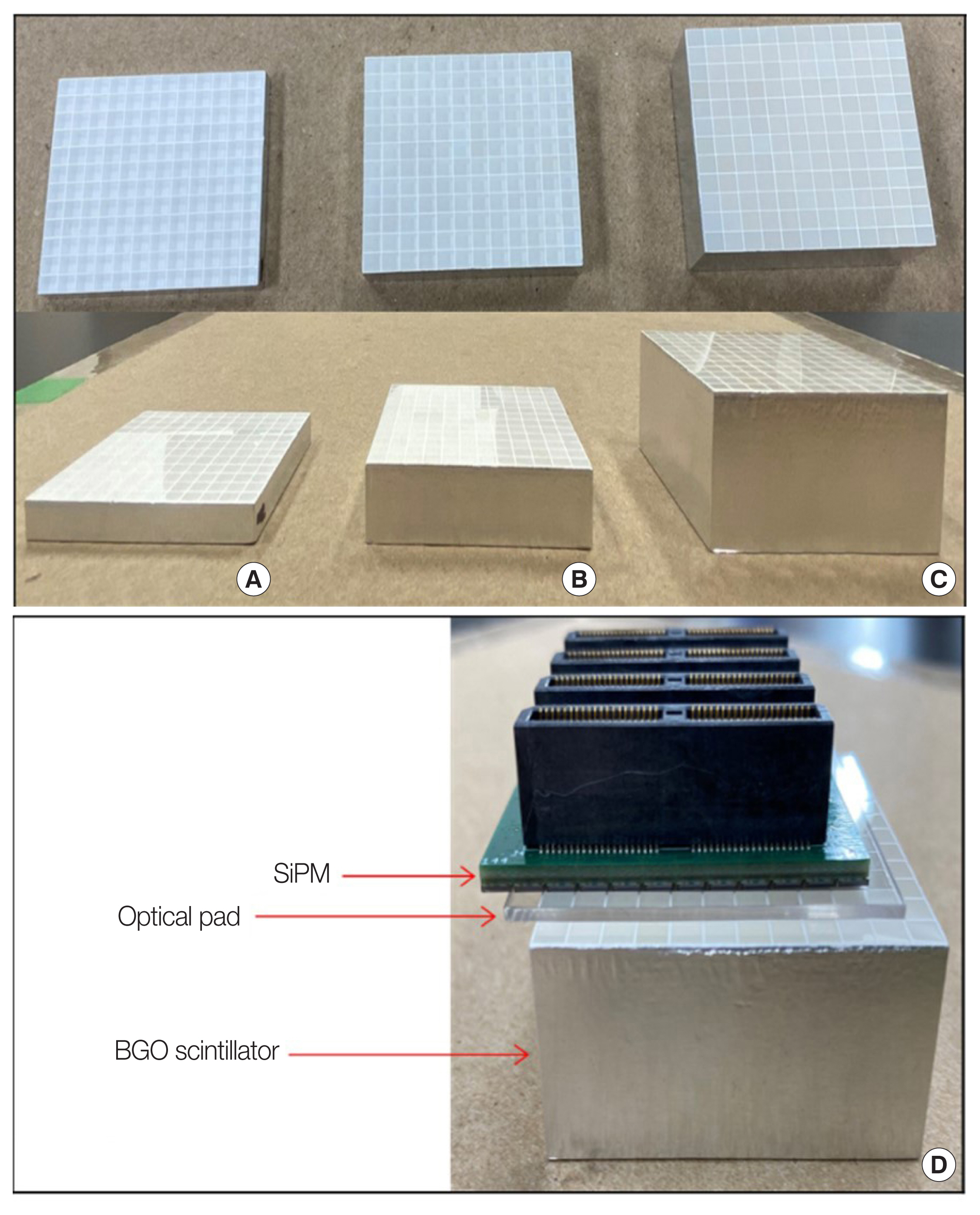
Fig. 3(A) View of the coded aperture mask printed by a three-dimensional (3D) printer with pieces of Pb inserted. (B) Pb shields are inserted into the side of the scintillator, as follows: 5 mm (left), 10 mm (middle), and 20 mm (right). (C) Coded-aperture design for various scintillator thicknesses. In each coded aperture mask, the mask-to-detector distance is 4.2578 cm, and all pixels have the same size of 4.105 mm. 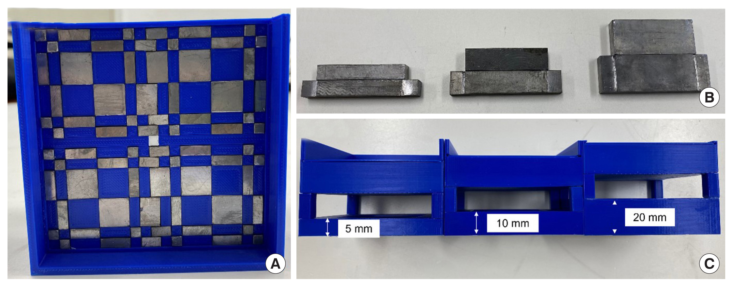
Fig. 4Cs-137 gamma-ray spectra acquired with the 50.8 mm× 50.8 mm×5 mm, 50.8 mm×50.8 mm×10 mm, and 50.8 mm× 50.8 mm×20 mm BGO scintillators coupled with 12×12 pixelated SiPM arrays. BGO, bismuth germanate; SiPM, silicon photomultiplier. 
Fig. 5Comparison of the peak pulse height according to the scintillator thickness. The peak-to-total ratio was 25.91% for the 5 mm-thick volume, 37.52% for 10 mm, and 45.06% for 20 mm. 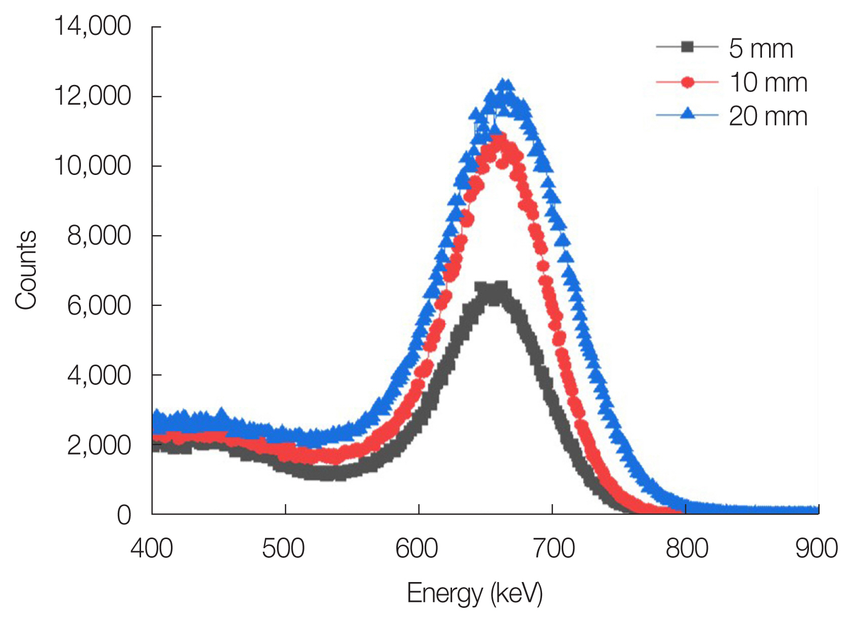
Fig. 6The 2D flood maps of (A) 50.8 mm×50.8 mm×5 mm, (B) 50.8 mm×50.8 mm×10 mm, and (C) 50.8 mm×50.8 mm×20 mm BGO scintillators coupled with 12×12 pixelated SiPM arrays. BGO, bismuth germanate; SiPM, silicon photomultiplier. 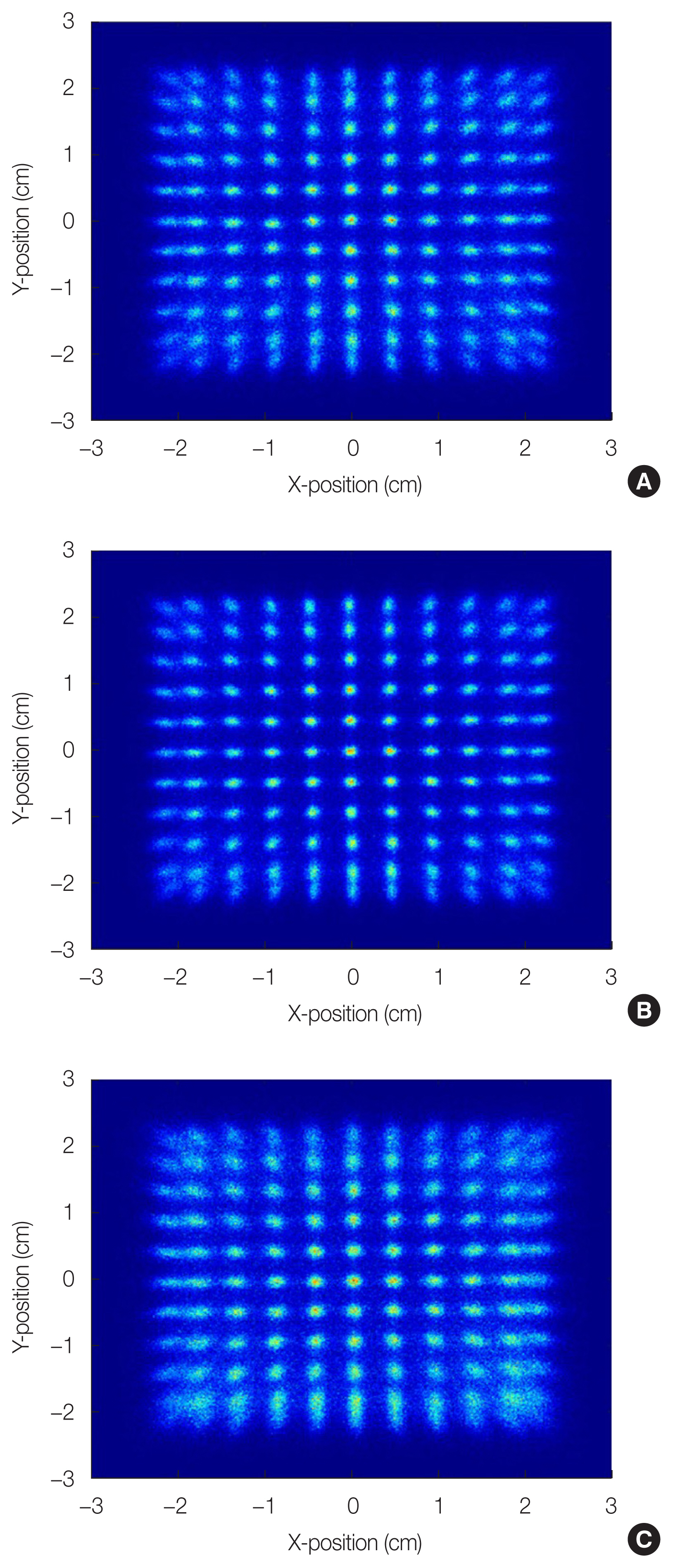
Fig. 7Normalized 1D row-sum profiles of the (A) 50.8 mm×50.8 mm×5 mm, (B) 50.8 mm×50.8 mm×10 mm, and (C) 50.8 mm×50.8 mm×20 mm BGO scintillators coupled with 12×12 pixelated SiPM arrays. BGO, bismuth germanate; SiPM, silicon photomultiplier. 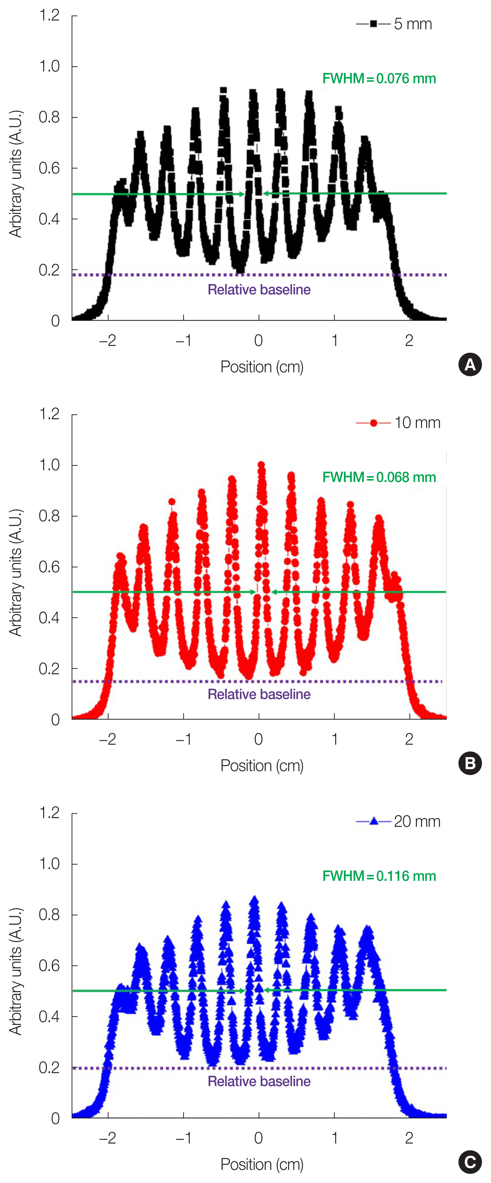
Fig. 8Images showing the separation of the two sources for the BGO scintillator sized (A) 50.8 mm×50.8 mm×5 mm, (B) 50.8 mm×50.8 mm×10 mm, and (C) 50.8 mm×50.8 mm×20 mm (Top) and 1D profiles (Bottom). The angular resolution for each thickness of the BGO scintillator was 9.5°, 8°, and 8.5°, respectively. BGO, bismuth germanate. 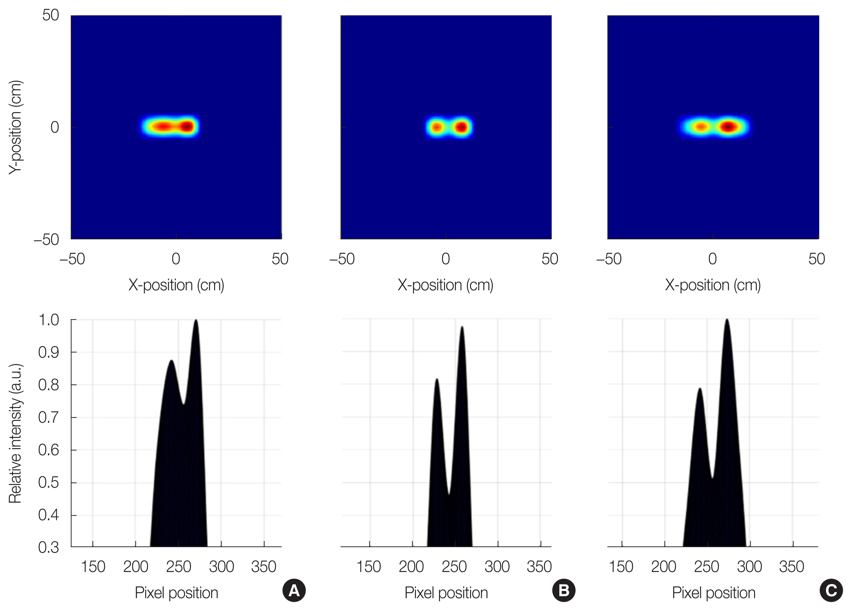
Fig. 9Images acquired for each field-of-view (FOV) with a scintillator size of (A) 50.8 mm×50.8 mm×5 mm, (B) 50.8 mm×50.8 mm×10 mm, and (C) 50.8 mm×50.8 mm×20 mm. 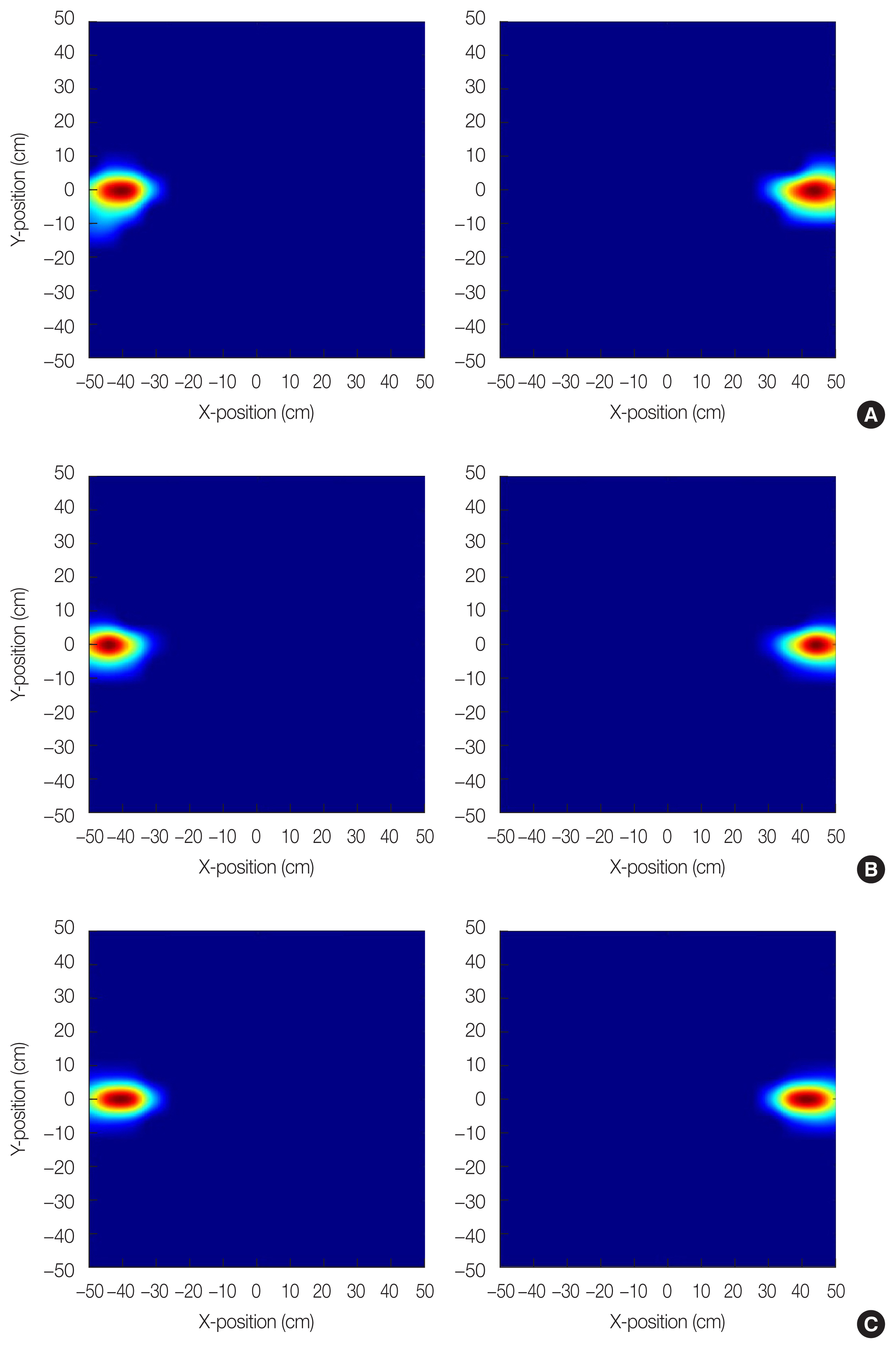
Fig. 10Graphical user interface (GUI) image acquired by counting for 11 seconds at a dose rate of 0.03 μSv/h of 137Cs using the BGO scintillator sized 50.8 mm×50.8 mm×10 mm. BGO, bismuth germanate. 
Fig. 11Reconstructed images for image quality evaluation. The size of the respective scintillators was (A) 50.8 mm×50.8 mm×5 mm, (B) 50.8 mm×50.8 mm×10 mm, and (C) 50.8 mm×50.8 mm×20 mm. 
Table 1General properties of GAGG(Ce) and BGO scintillators Table 2Energy resolution (R), PCR, and PVR according to the thickness of the BGO scintillator
Table 3Summary of image reconstruction performance of the BGO with different thicknesses compared with that of GAGG(Ce) scintillator arrays
|
|
||||||||||||||||||||||||||||||||||||||||||||||||||||||||||||||||||||||||||||||||||||||||||||||||||||||||||||||||||||||||||||||||||||||||